8
© 2002 Directed Electronics, Inc
1.
SSppeeaakkeerr OOuutt TTeerrmmiinnaallss
- Connect
the speakers to these terminals.
(Refer to the
Speaker Connection
section of this guide.)
2.
RReemmoottee TTuurrnn OOnn
- This terminal
turns on the amplifier when (+) 12
volt is applied to it. Connect it to
the remote turn on lead of the head
unit or signal source. If a (+) 12
voltremote turn lead is not avail-
able, a Remote Power Adapter
(P/N #55000) can be used to
supply a remote turn on signal. DO
NOT connect this terminal to
constant (+) 12 volt.
3.
PPoowweerr FFuusseess -
These fuse(s) protect
the amplifier against internal elec-
trical damage and are meant to
protect the amplifier only. All other
power connections should be fused
at the source.
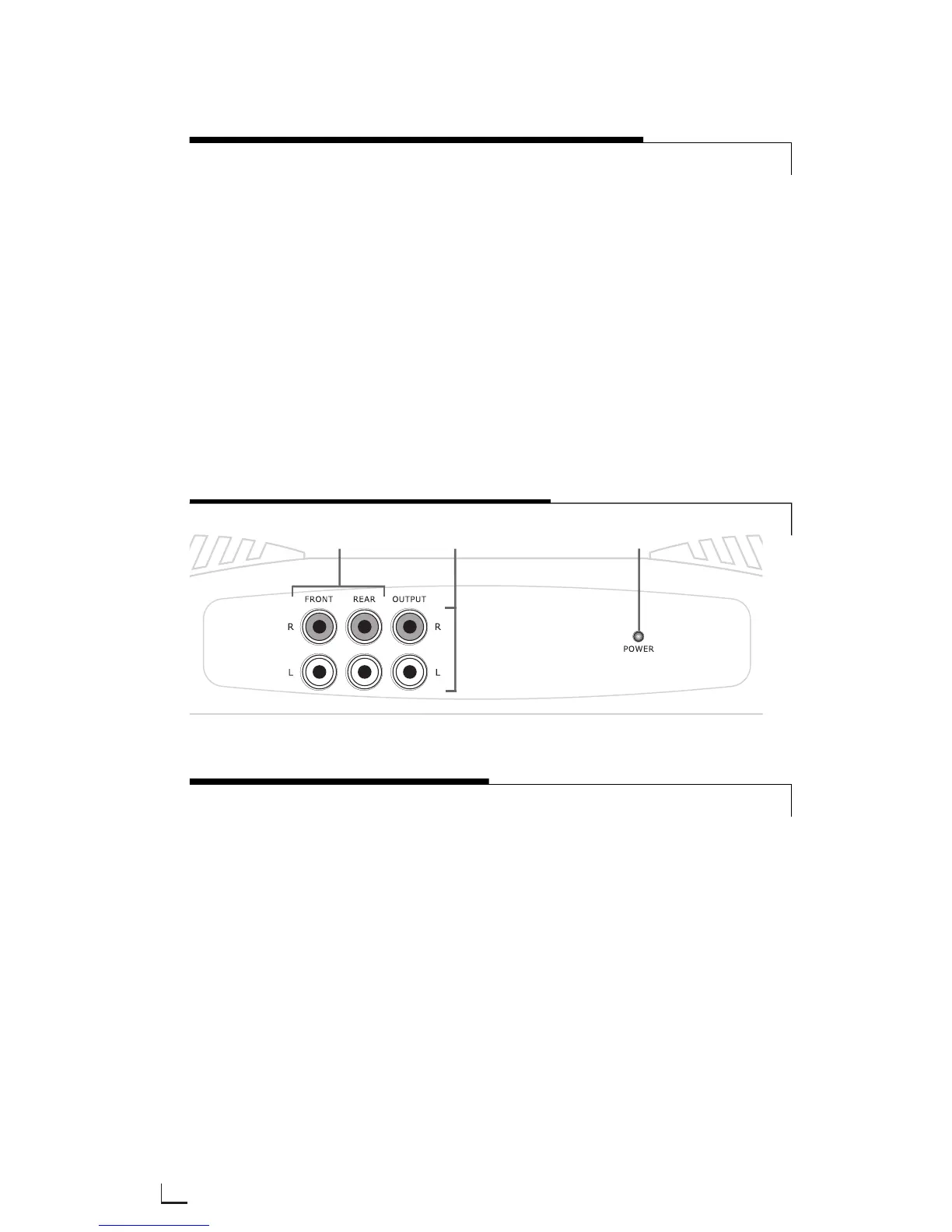
REAR PANEL CONNECTIONS
1.
RRCCAA IInnppuutt JJaacckkss -
Accepts line level
outputs from head units or signal
processors at voltages between
150mV and 8 volts.
2.
RRCCAA OOuuttppuutt JJaacckkss -
These pass
through RCA jacks can be used to
send a signal to a second amplifier.
On four, five, and six channel ampli-
fiers it is the summed stereo output
of the one through four-channel
inputs of the amplifier.
3.
SSttaattuuss LLEEDD
- Lights GREEN to indi-
cate the amplifier is on and oper-
ating normally, and will be off if the
amplifier shuts down due to short
circuit, DC offset, or overheating
detected by the on-board protection
circuitry.
FRONT PANEL CONNECTIONS/STATUS LED
FIGURE 1—AMPLIFIER CONNECTIONS 200.4/500.4 FRONT
2
1
3