Do you have a question about the Viper 791 XV and is the answer not in the manual?
| Range | Up to 1 mile |
|---|---|
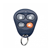
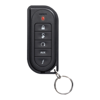
| Channels | 5 |
| Smartphone Control | No |
| Remote Start | Yes |
| Keyless Entry | Yes |
| Security System | Yes |
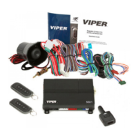
| Compatibility | Compatible with most vehicles |
| Battery Life | 1 Year |
| Additional Features | auxiliary output |
| Security Features | Stinger DoubleGuard shock sensor |
Important considerations and preparation steps before starting the installation process.
Post-installation checks and final steps to ensure proper system functionality.
Guidance on optimal placement for the siren to ensure security and prevent damage.
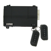
Recommendations for mounting the control module for best performance and accessibility.
Advice on best practices for installing the shock sensor for accurate detection.
Recommended placement for the valet/program switch for user access and discretion.
Guidelines for positioning the status LED for visibility and ease of identification.
Tips for discreetly locating the starter kill relay to prevent tampering.
Suggestions for mounting the relay satellite near the ignition switch for efficiency.
Instructions for locating and connecting a reliable constant 12V power source for the system.
Method for identifying the vehicle's ignition wire using a multimeter.
Procedure for locating the vehicle's starter wire with proper testing.
Guidance on identifying the accessory wire for powering vehicle features.
Steps to locate the tachometer wire for engine speed sensing.
How to find the wait-to-start wire in diesel vehicles for proper system operation.
Techniques for locating the parking light wire for system feedback.
Best locations and methods for testing the door pin switch circuit.
Procedure to test the neutral safety switch for correct operation and vehicle safety.
Details on bypassing Passlock I and II systems using specific bypass modules.
Information on bypassing Passkey III and other transponder-based immobilizer systems.
How standard transmitter buttons map to system functions like arming and disarming.
Default and programmable settings for fundamental system features.
Settings for more complex system functions and options.
Configuration options specifically for the remote start functionality.
Detailed explanations of basic system features and their operation.
In-depth descriptions of advanced system features and their settings.
Detailed explanations of remote start features and their configuration.
Step-by-step guide to diagnose system shutdowns using the LED.
Common alarm system issues and solutions for troubleshooting.
Specific problems and solutions related to the remote start function.