6
Rack & Limit Switch Installation
Power
Connect 115Volt AC to terminals power to terminals 6 & 7 at high power side of the control board. (See
Control board diagram at page 7)
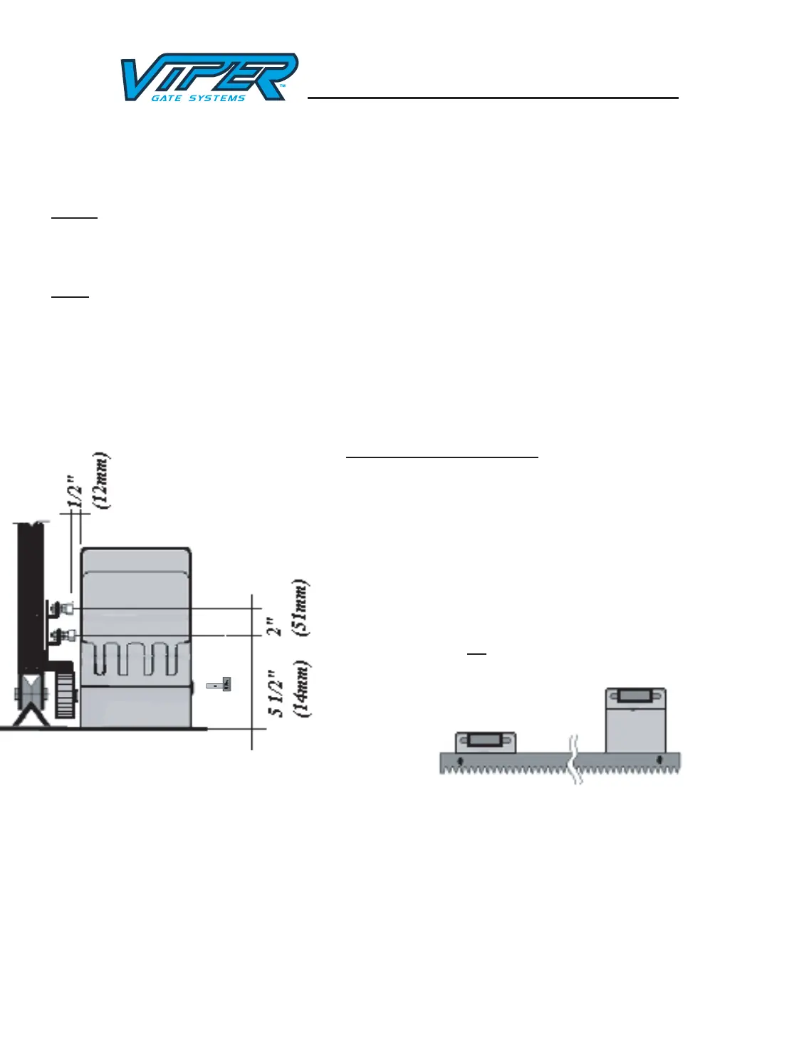
Rack
Loosen the clutch by the release key (Insert key and turn Counter Clockwise to release the clutch). Attach
the mounting bolts for the rack on the gate according to the specific position of the driving gear wheel and
make sure that the rack is horizontal. There must be a proper clearance between the gear and the rack @ 1/8”
(4mm). After installation of rack move the gate manually; make sure the gate slides smoothly.
Magnets For Limit Switch
Install the magnets for open & close position by mounting magnet
bracket to the gate. The shorter bracket is for open position and
longer bracket is for close position. The distance between the
magnet and the operator should be @ ½” (12mm) with the
operator cover on. To test the position of the magnets: Make sure
the operator clutch is disengaged (Counter turn release key clock
wise). Turn the power on (see control board information) move
the gate to open position the open position limit switch light 24
should come on, move the gate to close position the close position
limit switch light 25 should come on.
 Loading...