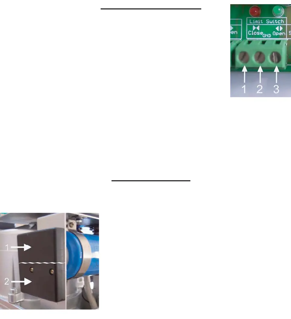
Limit Switch Connections
Terminal 1: Red wire will be connected here
Terminal 2: White wire will be connected here
Terminal 3: Green wire will be connected here
NOTE:
For left hand operation, reverse wires from terminals 1 and 3
Figure 7
Limit Switch Sensor
The limit switch sensor is divided into two parts as seen in
Figure 8.
To achieve your open limit, one of the magnets should
be mounted so that it is at the same height as Section
1 of the sensor.
To achieve your closed limit, the other magnet should be
mounted so that it is at the same height as Section 2 of the
ope
rator.
Figu
re 8
9