VNS2210 Amplifier & Controller Installation Guide – Version 2.00
VNS2210 Amplifier & Controller Installation Guide
VNS2210 Amplifier & Controller Installation
1. Determine the installation location for the VNS2210 device. Consider the following when determining the installation location:
Standard VNS2210 device is equipped with AC to DC power adaptor and requires a standard 110VAC or 220VAC power
outlet. The power adaptor consists of 6’ DC power cable and 6’ of AC power cord. Consider these cable lengths and the
distance between the power outlet and the VNS2210 device.
For VNS2210 devices equipped with VNS2256 option: The solar panel is equipped with 15’ feet of power cable. Consider
this cable length and the distance between the outdoor solar panel installation location and the VNS2210 device.
For VNS2210 devices equipped with VNS2267, VNS2268, VNS2261 or VNS2263 option: The intercom wall station is
equipped with 25’ feet of data cable. Consider this cable length and the distance between the intercom wall station
installation location and the VNS2210 device.
For VNS2210 devices equipped with VNS2264 option: The ambient noise level sensor is equipped with 10’ feet of data
cable. Consider this cable length and the distance between the ambient noise level sensor installation location and the
VNS2210 device.
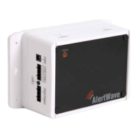
2. Position the VNS2210 device on the mounting surface and confirm that it is vertical to the floor.
Note
: When the device is installed properly, the LED should be on the left top corner (front view).
3. Secure the VNS2210 device to the wall using screws appropriate for the mounting surface (use 1.5”-2” long screws).
4. If an external antenna (2.5db or 3db gain) is used, install it on the BNC connector.
5. Connect the output devices to their respective port. Below are the available connector types that are installed on your device:
Strobe Lights: Strobe Light or 12VDC Controlled Device (for VNS2282 option, STROBE 1 and STROBE 2 ports)
Speakers: Speaker Audio Output (for VNS2281 option, SPEAKER 1 and SPEAKER 2 ports)
Intercom: Intercom Wall Station or Ambient Noise Level Control (for VNS2267, VNS2268, VNS2261, VNS2263 & VNS2264
options, INTERCOM port)
Audio: Line Level Audio Output with Dry-Contact Closure (for VNS2284 option, AUDIO and RELAY ports)
Relay: Dry-Contact Closure (for VNS2285 option, RELAY ports)
6. Connect the other end of each cable to the appropriate output device and verify proper connections.
7. Connect the power adaptor male connector to the POWER port of the VNS2210 device.
Note
: The VNS2210 devices should be protected from direct rain and snow, and if possible, from direct sun. Outdoor installation
should include an overhang to protect the VNS2210 device from direct rain, snow and sun.
VNS2267 & VNS2268 - Two Way Intercom Option
1. Before installation, consider the distance between the VNS2210 device and the VNS2267 or VNS2268 intercom wall station. The
VNS2210 device and the intercom wall station will be connected using the provided CAT5 cable (25’ long).
2. Follow steps 1-7 of the VNS2210 Amplifier & Controller Installation described above.
3. Disconnect the power source connector from the POWER port of the VNS2210 device.
4. Run the data cable between the VNS2210 device and the intercom wall station.
5. Connect the RJ45 data cable to the intercom wall station (Image 3).
6. Attach the intercom wall station to a single gang box using supplied 2 machine screws. For surface installation, use the
metal/wood screws (Image 2).
Note
: When mounting directly to wall surface (without gang box), remove the breakable data cable outlet (Image 3) and pass
the cable through the opening at the bottom.
7. Connect the other end of the cable (RJ45 connector) to the INTERCOM port on the VNS2210.
8. Connect the power source connector to the POWER port of the VNS2210 device.
9. Document the location and the serial number of the main VNS2210 device.
Note
: The serial number of the VNS2210 device is required for system programming.
10. To test communication with the base station, push the CALL button on the wall station.