2 DE6205
*Notes:
1.
If the CL-8A/CL-8A T is powered from a DC power supply,
the AUX and PANIC relays can be connected to terminal
7 (+).
2.
The PANIC and AUXILIARY outputs each include an 18
ohm resistor in series with the output. The maximum
current switching capability of each output is 100 mA.
**Caution! If the power supply provides AC, disregard
polarity. If the power supply provides DC, connect the
negative lead to terminal 6 and the positive lead to terminal 7.
***
Connect the remote request-to-exit switch or PIR contacts
across terminals 5 and 6. To light the red LED, connect the
12 or 24-Volt power supply across terminal 1 (+) and 2 (–).
To light the yellow LED, connect the 12 or 24-Volt power
supply across terminals 3 (+) and 4 (–).
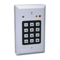
3.4 Tamper Switch TAMP-1 (optional)
This option includes a terminal block and a tamper switch on a
separate PC board. The tamper switch can be used in two ways:
A. To protect the CL-8A if tampering is attempted by removal of
the front part of the case. In this configuration, the tamper
actuator remains within the case, in physical contact with the
inner surface of the keypad’s back box.
B. To protect the CL-8A if tampering is attempted by removing the
unit from the wall or by removing the front of the case. This is
accomplished by opening the tamper knockout in the back box,
allowing the tamper actuator
to extend out of the back box
and contact the wall (see
Fig. 4).
Note: The tamper switch is
delivered as a separate item.
For ordering, specify TAMP-1.
Note: When using a tamper
switch, connect the tamper
N.C. terminals to a control
panel’s normally-closed, 24-
hour protection zone, or any
other system used to monitor
the tamper contacts
.
Fig. 4. Tamper Switch
Installation
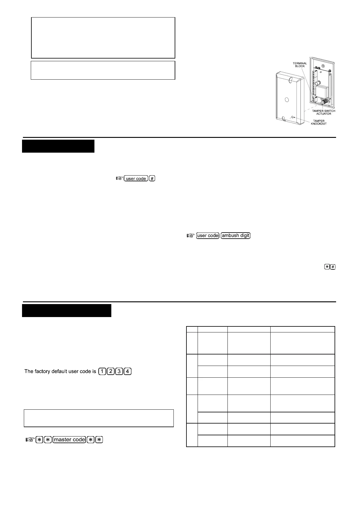
4. OPERATION
The main function of the CL-8A/CL-8A T is to recognize valid user
codes and respond according to pre-programmed instructions.
4.1 Keying Format
The user code is always followed by [#]:
4.2 Keypad Response
When a valid access code is keyed, the keypad responds by
activating the on-board relay (usually allocated to unlocking the
door), and/or activating the auxiliary circuit. Each of the 56
different access codes may be programmed to operate the on-
board relay, the auxiliary output or both. The green LED
illuminates for as long as the internal relay remains energized.
4.3 Latching the Relay
For special applications, the relay may be toggled, so that keying
the code once causes the relay to latch, and keying the code
again unlatches the relay.
4.4 Request to Exit
The REQUEST TO EXIT input activates the access control relay
to open the door from inside without keying a code, thereby
facilitating quick and simple exit from the protected area.
4.5 Automatic Reset
When keying user codes, the intervals between digits must not
exceed 5 seconds. Should the user exceed this time, or enter a wrong
code, an automatic reset results, requiring the user to wait a few
seconds and then to repeat entry of the security code again.
4.6 Lockout
A penalty lockout is provided to defeat “code-crackers”. Three wrong
entries result in a 10 minute lockout, during which an auxiliary output
is activated, but the keypad can be reset after 30 seconds by entering
a valid user code.
4.7 Access under Duress
If you are forced to access under threat, press the programmed
AMBUSH digit after the last digit of your code. This activates the
PANIC
output without arousing suspicion.
Enter the user code followed by the ambush digit
4.8 Operating Tips
A. Do not wait more than 5 seconds between successive
keystrokes, or else the keypad will reset.
B. To initiate an alarm without opening the door, press
simultaneously. This activates the PANIC circuit which is
usually connected to a silent alarm.
5. PROGRAMMING
Programming should be carried out as soon as installation is
completed. This provides a set of “instructions” which determines
how the keypad will react to various code inputs.
Programming changes can be made as many times as
necessary, but for security reasons, this operation is restricted to
the “master code” holder (the master user).
5.1 Accessing the Programming Menu
The programming menu is accessible only by the master user
As soon as code programming takes place, this default code is
automatically replaced by the first newly allocated code - No. 01.
Because user code No. 01 will become the new master code, it
should be assigned to the person in charge of security.
All code allocations should be recorded, and a User Code
Programming Chart - Appendix A, is supplied for this purpose.
Remember! To prevent unauthorized programming, it is
important to assign a new master code which should be used
for programming only.
To access the programming menu:
The green LED will start flashing slowly, indicating that the program-
ming menu is active. You can now select various programming functions
by pressing a number key from 1 to 5 (see Table 1).
Table 1. Programming Menu
No. Function Valid Entries Description
1
Programming
user codes &
their extent of
control
02 to 56 ⇒ # ⇒
[code] ⇒ # ⇒
[code (again)]
⇒ #
⇒ 1 or 2 or 3 ⇒ #
Assigns access codes (1 to 8
digit combination) to a person
or a group of users - see Para.
5.3 for exact procedure.
2
Setting the
relay timer
01 to 98
⇒ # Sets relay pull-in duration
between 1 and 98 seconds
Latching the
relay
99 ⇒ # Converts the relay to the
toggle mode (latch/unlatch)
3
Selecting the
AUX output
mode
1 to 7 ⇒ # The number entered
determines the operating
mode (see Table 2)
4
Deleting a
single user
code
User number,
02 to 56 ⇒ # ⇒
[master code] ⇒ #
User code corresponding to
the user number entered is
deleted.
Deleting all
user codes
⇒ # ⇒
[master code] ⇒ #
All user codes are deleted
together, except for code 01
5 Ambush digit 0 to 9 ⇒ # The programmed digit will be
valid until deleted or replaced
Delete
ambush digit
⇒ # The ambush digit is canceled
 Loading...