D-302893 5
4
B
5
6
C
D
E
F
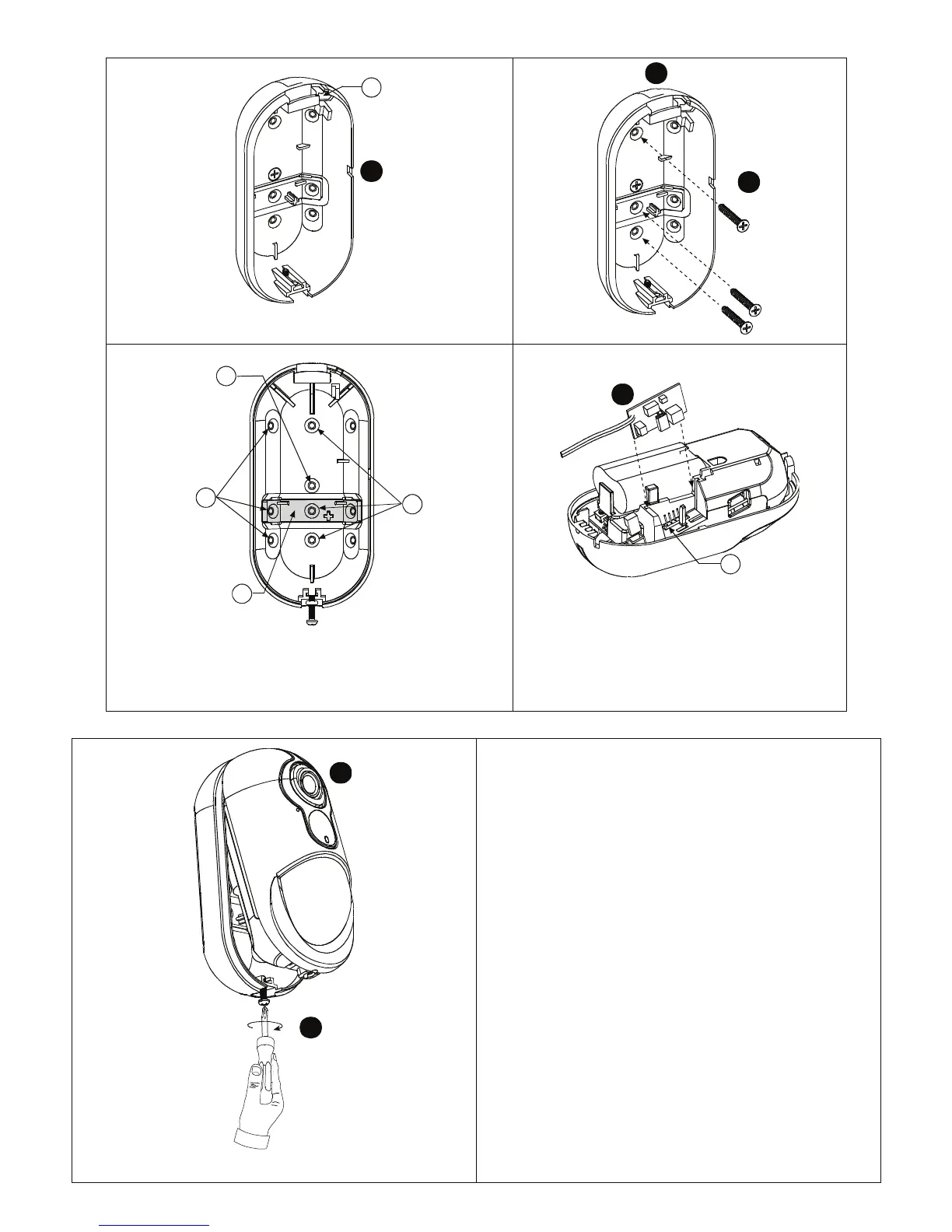
*CAUTION! THE BACK TAMPER SWITCH WILL NOT
PROTECT THE UNIT UNLESS THE BREAK-AWAY BASE
SEGMENT IS SECURED TO THE WALL WITH AT LEAST ONE
SCREW.
7
G
Figure 5a. Mounting on Wall
9
8
Figure 5b. Final Closure
1. Release screw.
2. Remove cover from base.
3. Position the battery in the battery holder and insert the battery
connector terminal into the battery connector.
4. For optional mains power supply: Break the cable entry
knockout and insert the mains cable.
5. Press the base against the wall at the selected mounting
position and mark the drilling points through the mounting
holes.
6. Drill 2 holes or 3 holes (for back tamper) and attach the base to
the wall using the screws.
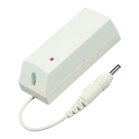
7. Slide the external power adaptor circuit into its connector.
8. Align the cover with the base.
9. Secure with screw.
A. Battery connector.
B. Cable entry knockout.
C. BR-1 Knockout
D. Mounting knockouts (for surface mounting)
E. Break-away base segment (shaded)
CAUTION! THE BACK TAMPER SWITCH WILL NOT
PROTECT THE UNIT UNLESS THE BREAK-AWAY BASE
SEGMENT IS SECURED TO THE WALL WITH AT LEAST
ONE SCREW.
F. Mounting knockouts (3 of 6 – for corner mounting).
G. Power adaptor circuit connector.