EasyManua.ls Logo

Visonic SD-304C PG2 User Manual

Visonic SD-304C PG2
8 pages
To Next Page IconTo Next Page
Page #1 background imageLoading...
Page #1 background image
D-304286 SD-304C PG2 Installation Instructions 1
1. INTRODUCTION
The SD- 304C PG2 is a wireless PowerG innovative shock detector with optional magnetic contact and auxiliary input interfacing with all PowerMaster
control panels, version 16 or higher. The SD-304C PG2 fits windows, doors, walls or roofs and is ideal for residential or commercial installations. It
detects and analyzes gross attacks or a series of low level shocks and provides early warning of any attempt of intrusion before a burglar actually breaks-
in.
A. Transmission LED
B. Magnet
Figure 1. External View
The detector incorporates:
l A shock / vibration piezoelectric sensor.
l Optional reed switch (with optional anti-mask sensor to prevent attempts at disabling it with an extra magnet).
l Optional auxiliary input to use with installer supplied contacts or other wired devices.
Installer added-value features:
l Digital display enables fast and easy shock level adjustment
l Full remote configuration from PowerMaster control panel or Monitoring Station saves the need to physically
access the shock detector for configuration
l Remote view of: Low Battery, front and back Tamper, Supervision
l An LED lights whenever alarm or tamper events are reported (the LED does not light while a supervision message is being transmitted).
2. INSTALLATION
2.1. Mounting
Figure 2. Base with P.C. Board Removed
A. Auxiliary input terminals
B. Back tamper switch
(behind P.C. board)
C. Battery clips
D. Break-away segment (for
back tamper
E. Digital display
F. Front tamper switch
G. Enroll button
H. LEDs indication
I. Reed switch
J. Up and down buttons
Refer to the Shock Detection Radius, in the Specifications section, according to the surface material used. Install the device in a location where a strong
shock impact is expected. The unit should be mounted on a flat surface and firmly fixed using both mounting screws.
For magnetic contact detection, it is highly recommended to attach the detector to the door or window on the fixed frame and the magnet to the movable
part (door or window). For optimal magnetic sensor activity and better security it is recommended to apply the magnet as close as possible to the
detector’s marked side.
Note: Once the cover is removed, a tamper message is transmitted to the control panel. Subsequent removal of the battery prevents transmission of
"TAMPER RESTORE", leaving the detector in permanent alert. To avoid this, press the tamper switch while you remove the battery.
Caution! Risk of explosion if battery is replaced by an incorrect type. Dispose of used battery according to manufacturer's instructions.
Attention! The unit has a back tamper switch (optional) under the PCB. As long as the PCB is seated firmly within the base, the switch lever will be
pressed against a special break-away base segment that is loosely connected to the base ("Figure 2. Base with P.C. Board Removed" above). Be sure
to fasten the break-away segment to the wall. If the detector unit is forcibly removed from the wall, this segment will break away from the base,
causing the tamper switch to open.
SD-304C PG2
PowerG, Wireless Shock and Contact detector with Wired Input
Installation Instructions
Question and Answer IconNeed help?

Do you have a question about the Visonic SD-304C PG2 and is the answer not in the manual?

Visonic SD-304C PG2 Specifications

General IconGeneral
Battery LifeUp to 5 years
Wireless ProtocolPowerG
Tamper ProtectionYes
TypeSmoke Detector
Frequency433 MHz
Operating Temperature-10°C to +55°C
Power Source3V Lithium battery
Operating Humidity10% to 93% (non-condensing)
MountingCeiling
CompatibilityPowerMaster systems

Summary

Introduction to Visonic SD-304C PG2 Detector

Shock and Contact Detector Overview

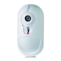
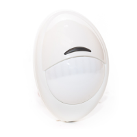
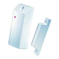
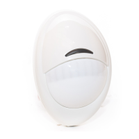
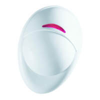
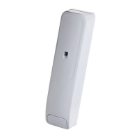
Details the PowerG shock and contact detector's features for windows, doors, and walls.

Installer Added-Value Features

Highlights digital display for easy adjustment and remote configuration capabilities.

Installation and Mounting Procedures

Mounting the Detector

Instructions for physically securing the detector base and cover, including tamper switch details.

Auxiliary Input Wiring

Connects auxiliary sensor contacts to the device terminals, detailing N.C., N.O., EOL, and DEOL configurations.

Device Enrollment Process

Step-by-step guide for enrolling the detector with the PowerMaster control panel.

Configuring Device Parameters

Sensitivity Threshold Configuration

Configure the sensitivity threshold of the shock detector via the panel.

Accumulated Shock Detection

Enable or disable accumulated shock detection mode from the panel.

Magnetic AM and Reed Switch Settings

Configure magnetic tampering detection and internal reed switch.

Auxiliary Input Configuration

Define the external auxiliary input type (Disabled, EOL, N.O., N.C., DEOL).

Local Calibration and Diagnostics

Local Operating and Calibrating

Adjust shock detector sensitivity locally using the digital display and buttons.

Local Diagnostics Test

Perform tests to verify detector reception and functionality.

Event Indications

Lists LED indications for tamper, shock, and auxiliary input events.

Compliance and Specifications

Compliance with Standards

Lists European and US standards the device complies with, including FCC and IC statements.

Shock Detection Radius Specifications

Details detection ranges for different materials like wood, glass, and concrete.

Operating Temperature and Humidity

Specifies the environmental operating limits for the device.

Warranty Information

Warranty Terms and Conditions

Outlines the 12-month warranty period and conditions for coverage.

Conditions to Void Warranty

Lists actions and conditions that will void the product warranty.

Items Not Covered by Warranty

Specifies items and costs that are excluded from warranty coverage.

Related product manuals