Installation Instructions
1. INTRODUCTION
The NEXT MCW is a microprocessor-controlled wireless digital PIR
detector, designed for easy installation, free of vertical adjustment.
It features a cylindrical lens with uniform detection sensitivity
throughout its operating range, up to 12 meters (40 ft), with wall
creep zone protection.
NEXT is a registered mark of Visonic Ltd.
The advanced True Motion Recognition™ algorithm (patented)
allows the NEXT MCW to distinguish between the true motion of an
intruder and any other disturbances which may cause false alarms.
An on-board motion event jumper determines whether 1 or 2
consecutive motion events trigger an alarm.
The NEXT MCW includes the following features:
• Incorporates a fully supervised PowerCode transmitter
• Patented sophisticated motion analysis algorithm - True Motion
Recognition (TMR™)
• Sophisticated frequency domain digital signal processing
• No vertical adjustment is needed
• Programmable motion event counter
• After detection, the detector disarms itself to save battery
power. It rearms (reverts to the ready state) if there is no
subsequent detection throughout the following 2-minute period
• An optional version provides better protection for systems
compliant with DD243. After initial detection, the detector is
capable of 7 additional detections for a period of 5 minutes.
Further detection is possible only if no movement occurs during
the following 2 minutes. The detector will revert to the initial
state if there is no movement for an additional 5 minutes.
• Very low current consumption
• Microprocessor-controlled temperature compensation
• Sealed chamber protects the optical system
• Front cover tamper switch.
• Back tamper switch (option)
• White light protection
• Elegantly styled, sturdy case
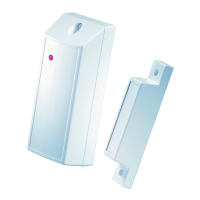
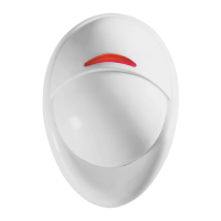
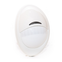
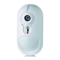
Figure 1. General View
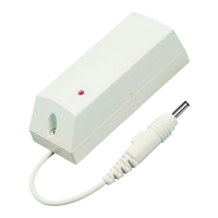
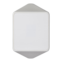
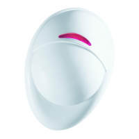
Figure 2. Inside View
For UL installations: The detector is for use with UL listed
control unit PowerMax+ only.
2. SPECIFICATIONS
OPTICAL
Detector Type: Dual element low-
noise pyroelectric sensor.
Lens Data
No. of Curtain Beams: 9 + 5
Max. Coverage: 12 x 12 m (40
x 40 ft) / 90°
ELECTRICAL
Internal Battery: 3V Lithium
battery, type CR-123A. For UL
installations, use Panasonic or
Sanyo only.
Nominal Battery Capacity:
1450 mA/h.
Standby Current Drain: approx.
0.025 mA.
Transmit Current Drain: 20 mA
(including LED).
Battery Life (with LED on):
Typically over 3 years.
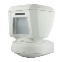
Figure 3. Maximum
Coverage Pattern
Battery Power Test: Performed immediately upon battery
insertion and periodically after every several hours.
FUNCTIONAL
True Motion Event Verification: 2 position selector - 1 (OFF) or
2 (ON) motion events.
Alarm Period: 3 seconds.
Visual Indications:
LED Lights for about 3 seconds upon transmission of alarm &
tamper messages and upon motion detection in the walk test
mode.
LED Flashes during the power-up stabilization period, or
after restoring (pressing) the tamper switch.
LED Does not light upon transmission of supervision
messages.
Rearm Timer: Rearms the detector 2 minutes after the last alarm.
Timer disabled in the walk test mode – not applicable for the
DD243 version (see section 1).
WIRELESS
Frequency (MHz): 315 (U.S. version), 433.92, 868.95, 869.2625
or other frequencies according to local requirements.
Transmission Sequence: 3 data bursts at variable intervals
within 3 seconds.
Encoding: 24-bit ID, over 16 million possible combinations.
Total Message Length: 36 bits.
Tamper Alert: Reported when a tamper event occurs and in any
subsequent message, until the tamper switch is restored.
Supervision Message: Signaling at 60-minute intervals (U.S.
version) or 15 minute interval (UK version), or according to the local
standards.
MOUNTING
Height: 1.8 - 2.4 m (6 - 8 ft).
Installation Options: Surface or corner.
ACCESSORIES:
BR-1: Surface mounted swivel bracket, adjustable 30° down and
45° left/45° right.
BR-2: BR-1 with a corner adapter
BR-3: BR-1 with a ceiling adapter
ENVIRONMENTAL
RFI Protection: >20 V/m up to 1000 MHz.
Operating Temperatures: -10
°C to 50°C (14°F to 122°F).
Storage Temperatures: -20
°C to 60°C (-4°F to 140°F).
Compliance with Standards: Designed to meet FCC Part 15
and Directive 1999/5/EC of the European Parliament.
EN 50131-2, Grade 2, Class II
PHYSICAL
Size
(H x W x D): 94.5 x 63.5 x 53.0 mm (3-11/16 x 2-1/2 x 2-1/16”).
Weight (with battery): 70 g (2.5 oz).
Color: White.
PATENTS: U.S. Patents 5,693,943 z 6,211,522 z D445,709
(another patent pending).