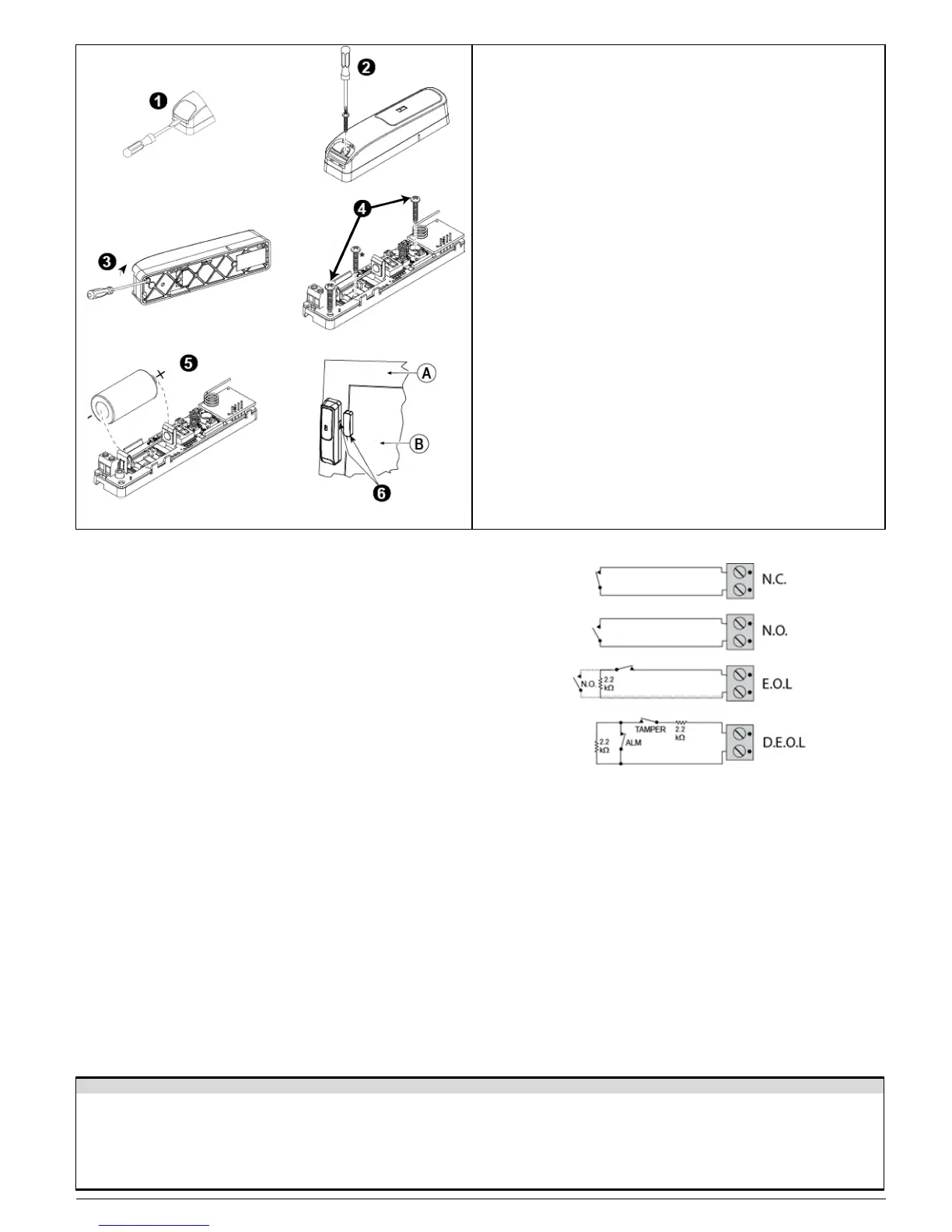
Figure 3. Mounting
Note: Use a manual screwdriver only.
1. Insert a flat-edged screwdriver into the slot and push upward to remove
the screw cover.
2. Remove screw.
3. Separate base from cover.
4. Secure the base to the mounting surface using only the screws supplied
in the package.
Caution! Do not remove the PCB to mark holes but use the paper
model included with the detector.
Caution! Do not use double-sided tape, as this will tend to insulate the
detector from vibrations.
Caution! Do not over tighten screws to avoid damaging the PCB.
5. Insert the battery while observing polarity.
6. Mount the magnet near its location mark with 2 screws.
A. Fixed frame
B. Moving part
Note: 868 MHz device is illustrated in the example. The same mounting
procedure should be performed for 433 MHz and 915 MHz devices.
* This additional screw is used for back tamper only.
2.2. Auxiliary Input Wiring
A. Connect the auxiliary sensor contacts across the SD-304C PG2
auxiliary input terminals.
Note: Maximal guaranteed cable length is 10m (33 ft.).
B. If the auxiliary input of the SD-304C PG2 is defined as a Normally
Closed (N.C.) type, series connected N.C. sensor contacts must be
used exclusively. An alarm message is transmitted once the loop is
opened.
C. If the auxiliary input of the SD-304C PG2 is defined as a Normally
Open (N.O.) type, parallel connected N.O. sensor contacts must be
used exclusively. An alarm message is transmitted once the loop is
closed.
D. For End of Line (EOL) supervision:
Normally Closed (N.C.) or Normally Open (N.O.) sensor contacts
can be used, as shown in Figure 4. A 2.2kΩ E.O.L. resistor must
be wired at the far end of the zone loop. An alarm message is
transmitted once the loop is opened or short circuited.
E. For Double End of Line (DEOL) supervision:
Two Normally Closed (N.C.) sensor contacts can be used, as
shown in Figure 4. Two 2.2kΩ E.O.L. resistors must be wired at the
far end of the zone loop which is opened or short circuited. Event
messages are transmitted according to connected inputs, for
example, Alarm or Tamper contacts.
Figure 4. AUX Input Wiring Examples
2.3. Enrollment
Refer to the PowerMaster panel's Installer's Guide and follow the procedure under the "02:ZONES/DEVICES" option of the Installer Menu. A general
description of the procedure is provided in the following flow chart.
Step 1 Step 2 Step 3 Step 4
Enter the Installer menu and select
“02:ZONES/DEVICES”
Select "ADD NEW DEVICE" See
Note 1
Enroll the detector: press the enroll
button and then release it as soon as
Select the desired detector
number for the new flood detector
D-304286 SD-304C PG2 Installation Instructions 2
the yellow LED lights, or, enter the
device ID (on the back of device)