2 D-302182 PGM-5 Installation Instructions
2. SPECIFICATIONS
2. SPECIFICATIONS2. SPECIFICATIONS
2. SPECIFICATIONS
Number of Outputs: 5
Output Type: Solid State Relay – dry contact.
Predefined Output State: N.O. or N.C. programmable (by DIP switch).
Maximum Load Current: 100 mA
Maximum Peak Current: 350 mA @10 ms
Output Resistance R
ON
: 16Ω max. @I
L
= 100 mA
N.O. Leakage Current: <1 uA
Maximum Load Voltage: 15 V
Operating Temperatures: 0°C to 50°C (32°F to 122°F)
Compliance with Standards: EN 50130-4
3.
3. 3.
3. MOUNTING AND WIRING
MOUNTING AND WIRINGMOUNTING AND WIRING
MOUNTING AND WIRING
In the PowerMax Pro, PowerMaxComplete, PowerMaster-30 G2 and PowerMaster-33 G2 control panels, press the PGM-5 module into the
marked location (see Figures 4a, 4b and 4e) until a click is heard.
In the PowerMaxExpress and PowerMaster-10 G2 control panels, use the two screws to fasten the PGM-5 module into the marked location, as
illustrated in Figure 4c and 4d.
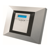
POWERMAX PRO
Connect one side of the flat cable
into the PGM-5 connector and the
other side into the PowerMax Pro
PC connector
Flat cable
PowerMax Pro
PC Connector
PGM-5
Front unit
Back unit
Wiring*
Figure 4a – PGM-5 Mounting and Wiring in PowerMax Pro Control Panel
* It is strongly recommended to route the cable as shown to prevent interference which may occur if routed too close to the control panel's antennas.
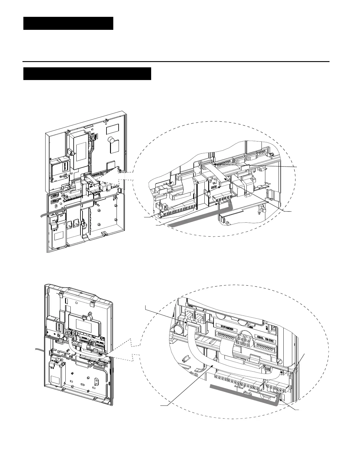
POWERMAXCOMPLETE
Connect one side of the flat cable into the
PGM-5 connector and the other side into the
PowerMaxComplete BBA connector
Flat cable
PowerMaxComplete
BBA Connector
PGM-5
Front unit
Back unit
Wiring*
Figure 4b – PGM-5 Mounting and Wiring in PowerMaxComplete Control Panel
* It is strongly recommended to route the cable as shown to prevent interference which may occur if routed too close to the control panel's antennas.
 Loading...