CONNECTING THE FEEDER CABLE
To connect the feeder cable to the hob it is necessary to carry out the following opera-
tions:
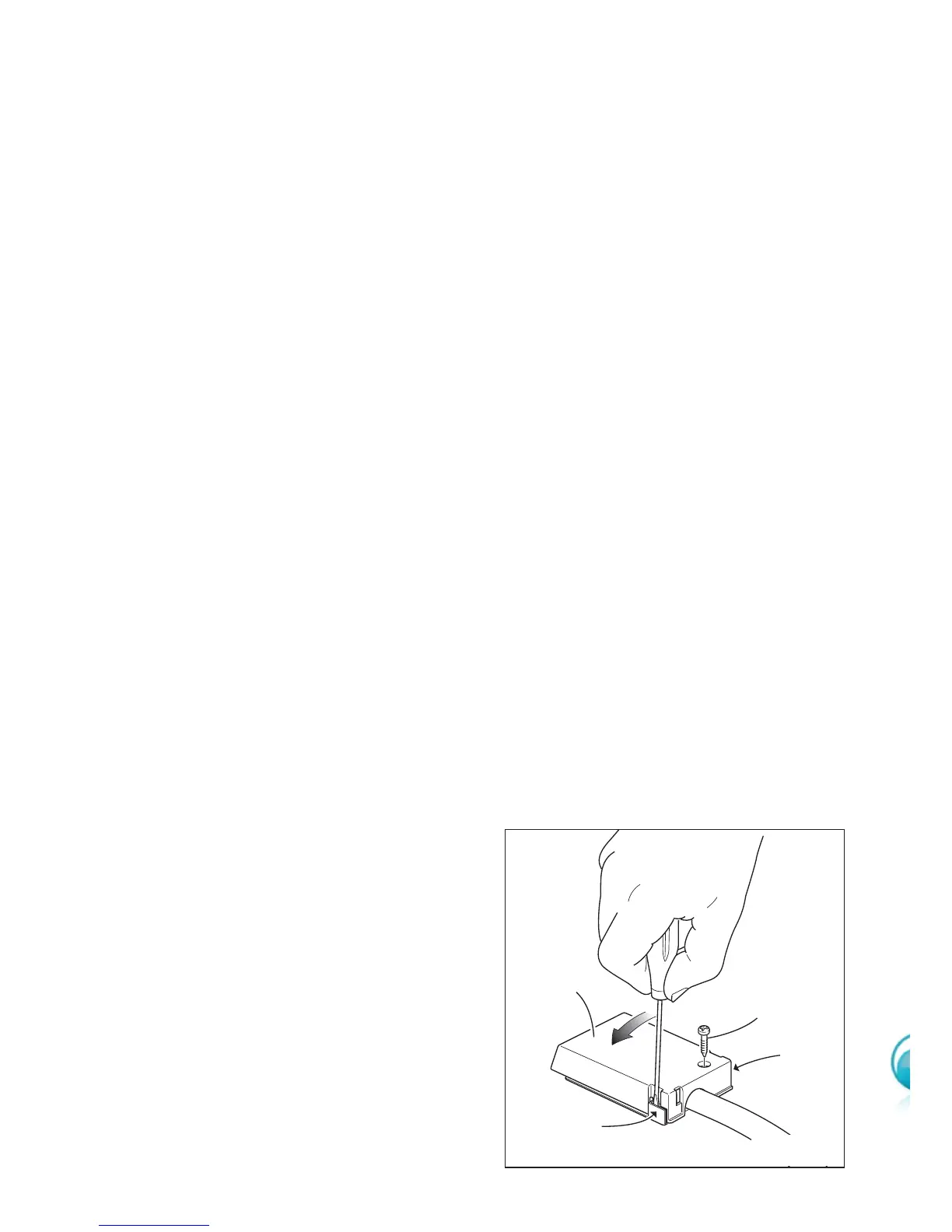
• Unscrew the screw A of the terminal board at the bottom of the hob (fig. 4.5).
• Unlock the 2 clips B and open the cover C.
• Unscrew the screw D and open completely the cable clamp E (figs. 4.7 - 4.8 - 4.9).
• Position the U bolts F onto terminal board G (figs. 4.7 - 4.8 - 4.9) according to the
diagrams in fig. 4.6.
• Connect the phase and earth wires to terminal board G according to the diagrams in
fig. 4.6.
• Strain the feeder cable and block it with cable clamp E (by screwing screw D).
• Close the cover C of the terminal board G and block it with the screw A.
FEEDER CABLE SECTION
“Type H05VV-F or H05V2V2-F or H05RR-F”
For 60 cm and 80 cm models:
220-240 V
~ 3 x 2.5 mm
2
(**)
380-415 V 3N
~ 5 x 1.5 mm
2
(**)
380-415 V 2N
~ 4 x 2.5 mm
2
(**)
For 90 cm models:
220-240 V
~ 3 x 4 mm
2
(**)
380-415 V 2N
~ 4 x 2,5 mm
2
(**)
380-415 V 3N
~ 5 x 2.5 mm
2
(**)
21
A
B
C
B
Fig.4.5
(**)
Connection with wall box connection.
– Diversity factor applied
–A diversity factor may be applied to
the total loading of the appliance only
by a suitably qualified person.