4
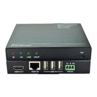
Transmitter Panel Description
1. Power LED: The LED illuminates green when power is applied and is off when no
power is present.
2. LINK LED: The LED illuminates blue when there is a valid HDBaseT connection
with the receiver. The LED is off when there is no valid link.
3. HDMI LED: The LED illuminates blue when there is HDMI video input with HDCP.
It will blink blue when there is HDMI video input without HDCP and will be off
when there is no HDMI video traffic.
4. RS232: 3-pin terminal block for bi-directional RS232 pass-through or RS232 relay
control.
5. L+R OUT: 3-pin terminal block to connect an audio play device (e.g. amplifier) for
audio de-embedding from HDMI input stream.
6. SPDIF OUT: Toslink connector to connect an audio play device (e.g. amplifier) for
audio de-embedding from HDMI input stream.
7. HDBT OUT: RJ45 port to connect the HDBT IN port of receiver by CATx cable.
The HDCP LED illuminates green when the video contains HDCP content, or
blinks green when the video has no HDCP content. The LINK LED illuminates
orange when there is a valid HDBaseT link between the transmitter and the
receiver.
8. HDMI IN: Type-A female HDMI input port to connect an HDMI source device.
9. DC 24V: Locking power port for 24V DC power adapter connection.
L RTx Rx
HDCP LINK
1
2
3
4
5
6
7
8
9