3
English
Installation
II
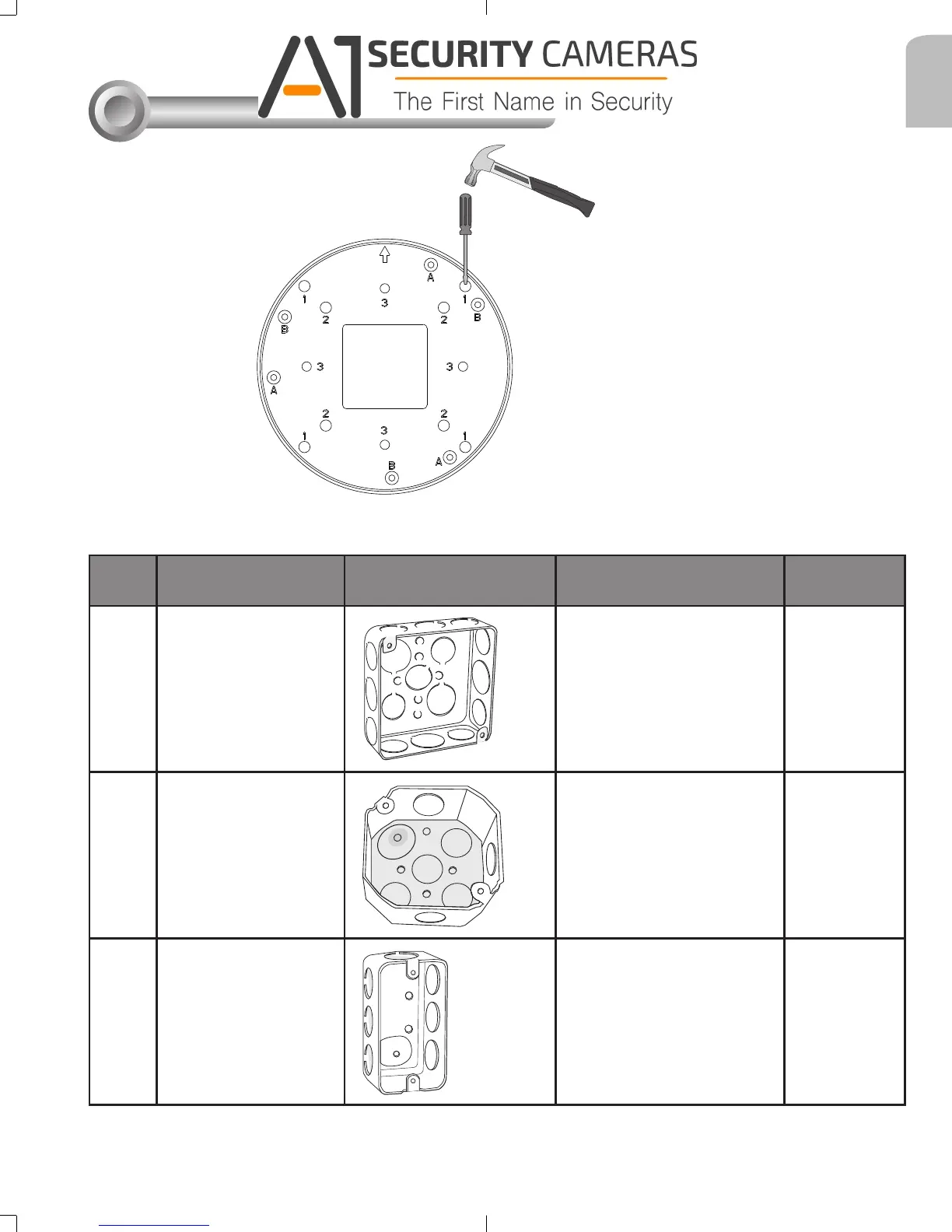
Above are the locations of different groups of mounting holes for matching different junction
boxes:
Hole
Type
Applicable Box Drawings Screw No. of
screws
1
4" square box
#8-32, L15
(User-supplied)
2
2
4" octagon box
#8-32, L15
(User-supplied)
2
3
1" single gang box
#6-32, L15
(User-supplied)
2
Mounting Hole Denitions
User a hammer and screwdriver to open the
knock out holes you prefer to use.
625031700G_AM-514_ig_VVTK_rev1.0_20150910.indd 3 2015/9/10 上午 11:20:06
Available from A1 Security Cameras
www.a1securitycameras.com email: sales@a1securitycameras.com