4
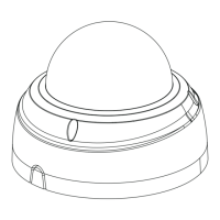
Installing the Mounting Cap
NOTE:
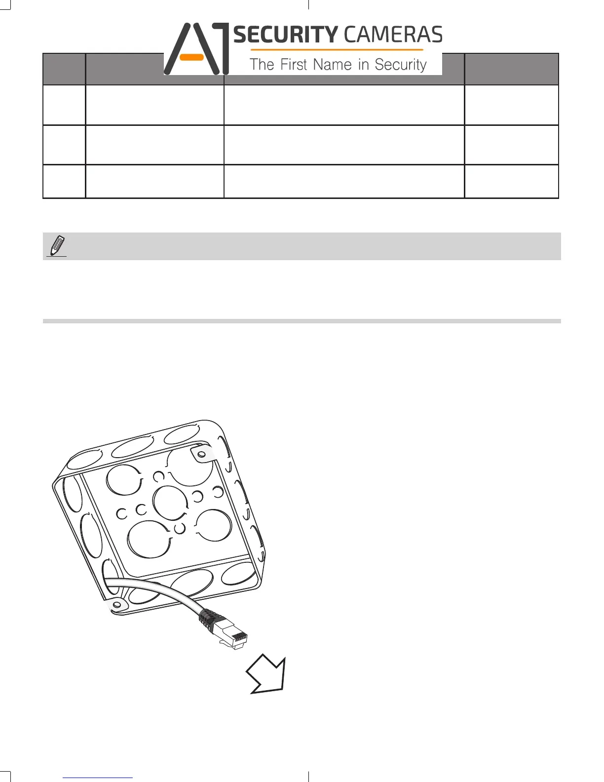
1. Route cables before you secure the accessories to a wall.
2. For details on the cable connections with network cameras, please refer to their Quick
Installation Guide.
Hole
Type
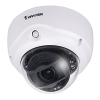
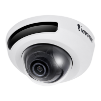
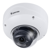
Applicable Cameras Screw No. of screws
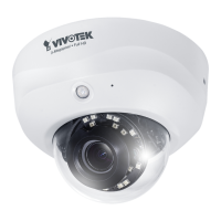
A
FD9171, FD816B,
FD8182
#8-32, L15 (User-supplied)
2
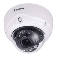
B
FD8167, FD8138-H
#8-32, L15 (User-supplied)
2
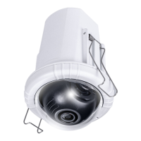
1
FE8174
#6-32, L15 (User-supplied) + copper spacers
2
1. Route cables through the junction box.
625031700G_AM-514_ig_VVTK_rev1.0_20150910.indd 4 2015/9/10 上午 11:20:06
Available from A1 Security Cameras
www.a1securitycameras.com email: sales@a1securitycameras.com