EN - 4
Network Deployment
3
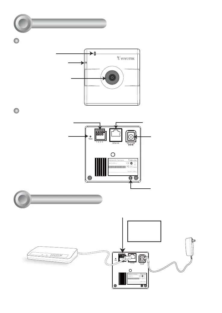
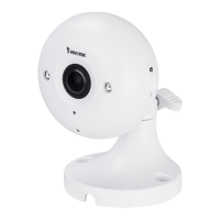
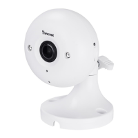
Physical Description
2
Front Panel
Back Panel
Status LED
Privacy Button
Lens
Built-in Microphone
MAC:0002D132C353
IP8132
This device complies with part 15 of the FCC rules. Operation is subject to the following two conditions:
(1)This device may not cause harmful interference, and
(2) this device must accept any interference received, including interference that may cause undesired operation.
Pat. 6,930,709
General I/O Terminal Block
Recessed Reset Button
Power Cord Socket
Ethernet 10/100 RJ45 Socket
MAC:0002D132C353
IP8132
This device complies with part 15 of the FCC rules. Operation is subject to the following two conditions:
(1)This device may not cause harmful interference, and
(2) this device must accept any interference received, including interference that may cause undesired operation.
Pat. 6,930,709
POWER
COLLISION
LINK
RECEIVE
PARTITION
1
2
3
4
5
3. Connect the supplied
power cable from the
camera to a power
outlet.
2. Connect the camera to a switch
via Ethernet cable.
● Use Category 5 Cross Cable
when Network Camera is directly
connected to PC.
1. If you have external devices such as sensors and alarms, make connections from
general I/O terminal block.
4: Power
3: Digital output
2: Digital input
1: Ground