VIVOTEK
User's Manual - 9
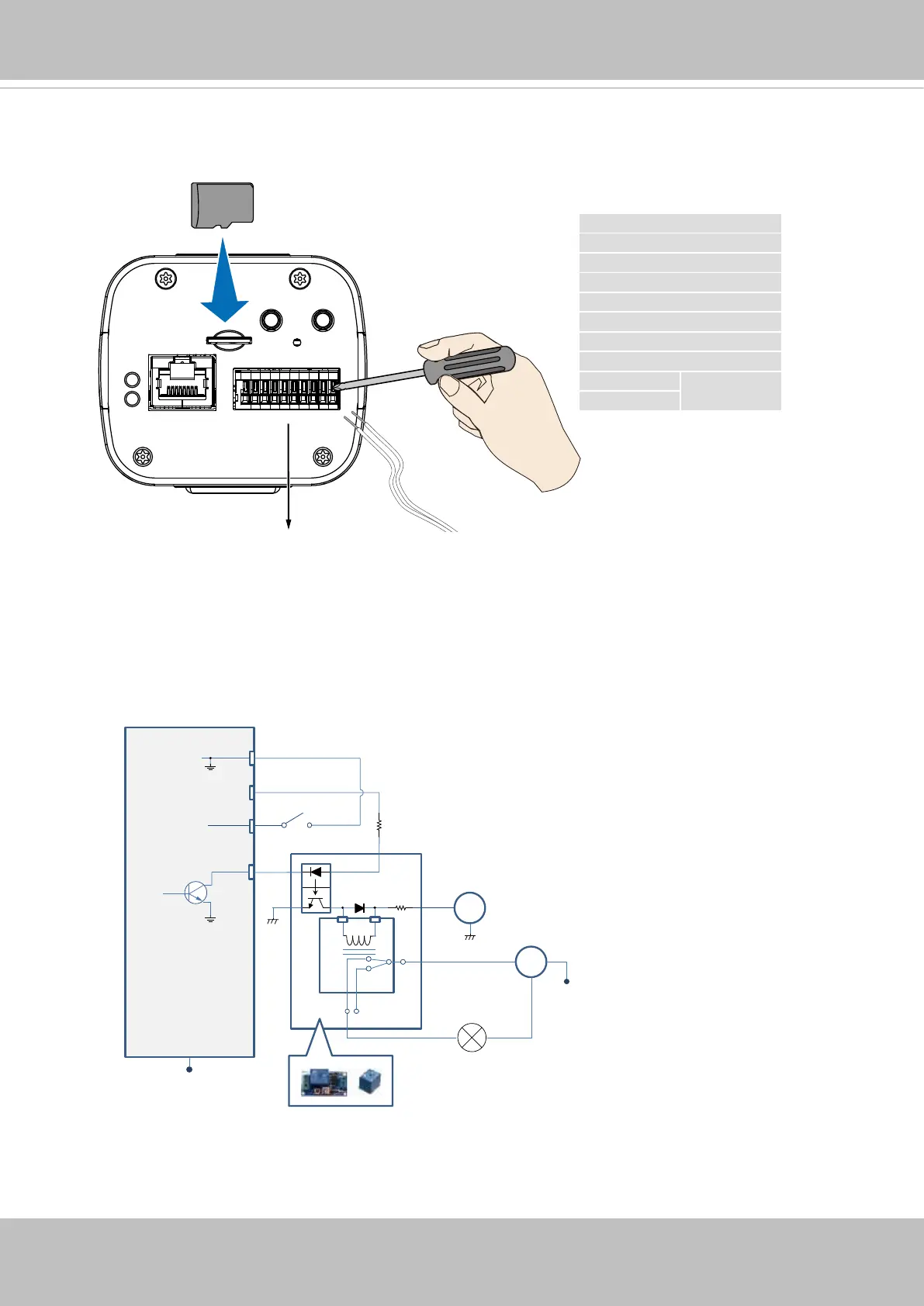
7. Install a MicroSD card, and, if preferred, connect DI/DO wires to the terminal block The
AC/DC pins can accept either 12V or 24V power input with no polarity.
The DO pin can provide a 5V output, and the max. load is 50mA.
M
icro
SD
DO+ (+5V)
DO-
DI1+
DI2+
DI3+
DI- (common GND)
RS485-
RS485+
AC/DC+ pw
12V or 24V
AC/DC- pw
DI/DO Diagram
DI-
DO+
DI+
DO-
Switch
External Device
External DC power
Dry contact with external DC power source to supply a relay. Dry contact is the safest connecon
to protect devices.
NC
NO
Relay
Photo
Coupler
DC
DC 0V
DC 0V
External AC power
with Protected Earth
AC
PE
PE