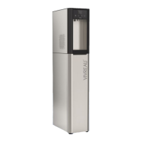
• Attach the drain hose of the drip tray to the drip tray connection.
• Attach hoses for H2O and CO2 to the device. Provide all connectors with safety clips (image 1).
• Remove the device feet of the table-top device.
• Feed the hoses through the opening in the base cabinet (image 2). Place the device on the base
cabinet and x it with 4 screws (image 3).
Step 5 — Place the device on the base cabinet
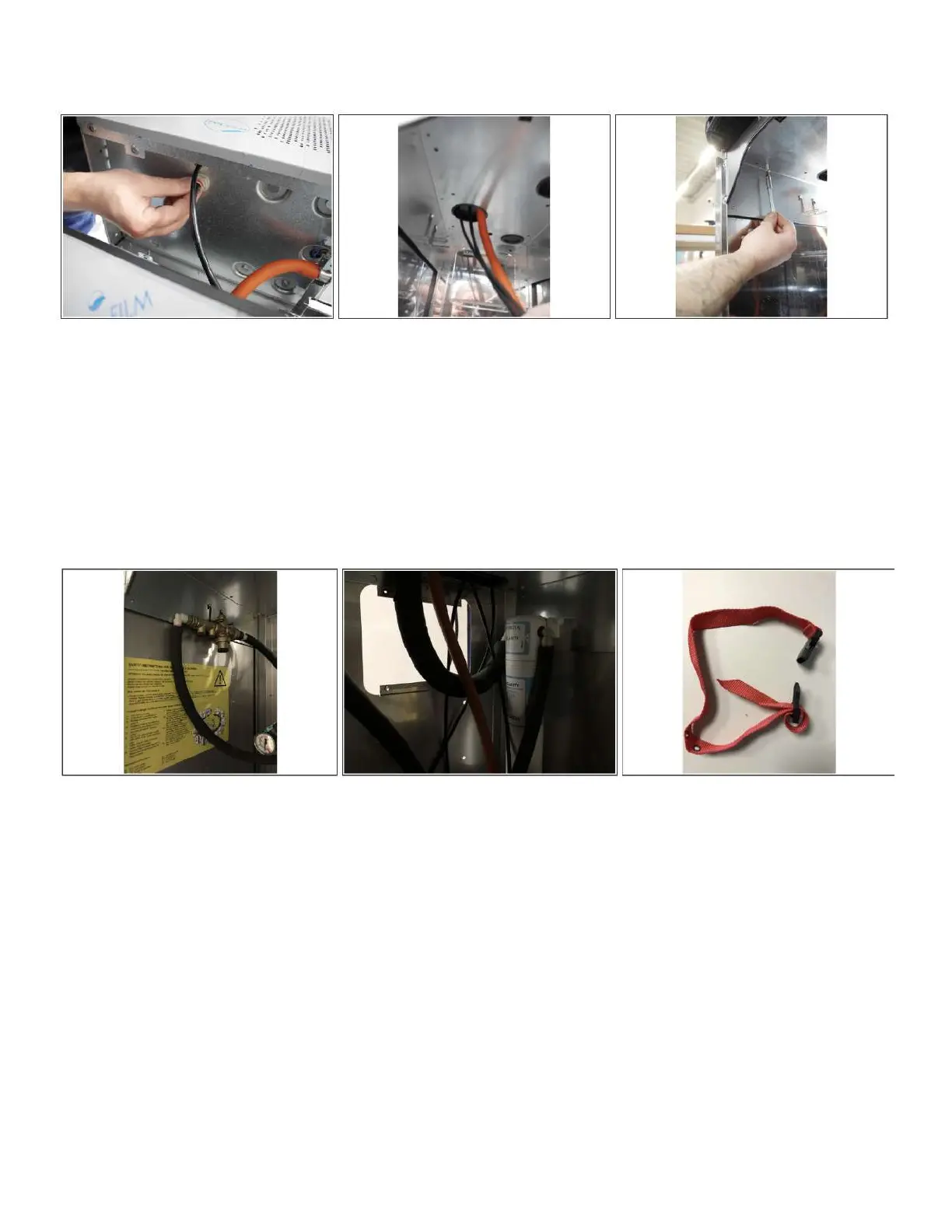
• The Aquastop is mounted directly on the corner water supply ½” ball valve.
• The water pressure reducer is mounted using the supplied retaining clip at the top left of the base
cabinet (image 1).
• Fasten the lter head at the top right. Insert angle connector and secure with safety clips. Insert lter
(image 2).
• Fasten the CO2 strap with 2 screws on the right side.
• Position the CO2 bottle in the cabinet and secure it with the retaining strap (image 3).
• To avoid corrosion, it is recommended to use a rubber mat between the CO2 bottle and the oor.
• Attach a yellow CO2 information sign in the respective national language in the base cabinet so that it
is clearly visible (image 1).
Step 6 — Installation of the components
 Loading...