·
·
·
1.
2. .
3.
The requirements to connecting cables between the doorstation / control
unit, commutator and monitors are given in operating instructions on a corresponding doorstation / control unit of
your multi-apartment video doorphone.
Carry out as described below:protective earthing connection
Connect cables following the examples of wiring diagrams refer to the section
For connections,
Lay a trunk protective conductor with yellow-green insulation and copper wire cross-section of 1.5 mm from the
main protective conductor of the building to the last BK-4AV device in the video circuit, which has connected
monitors powered from switching adaptors.
Connect the trunk protective conductor to the main protective conductor of the building
protective connected monitors powered from switching
adaptors to the trunk protective earthing conductor (see the sections
and
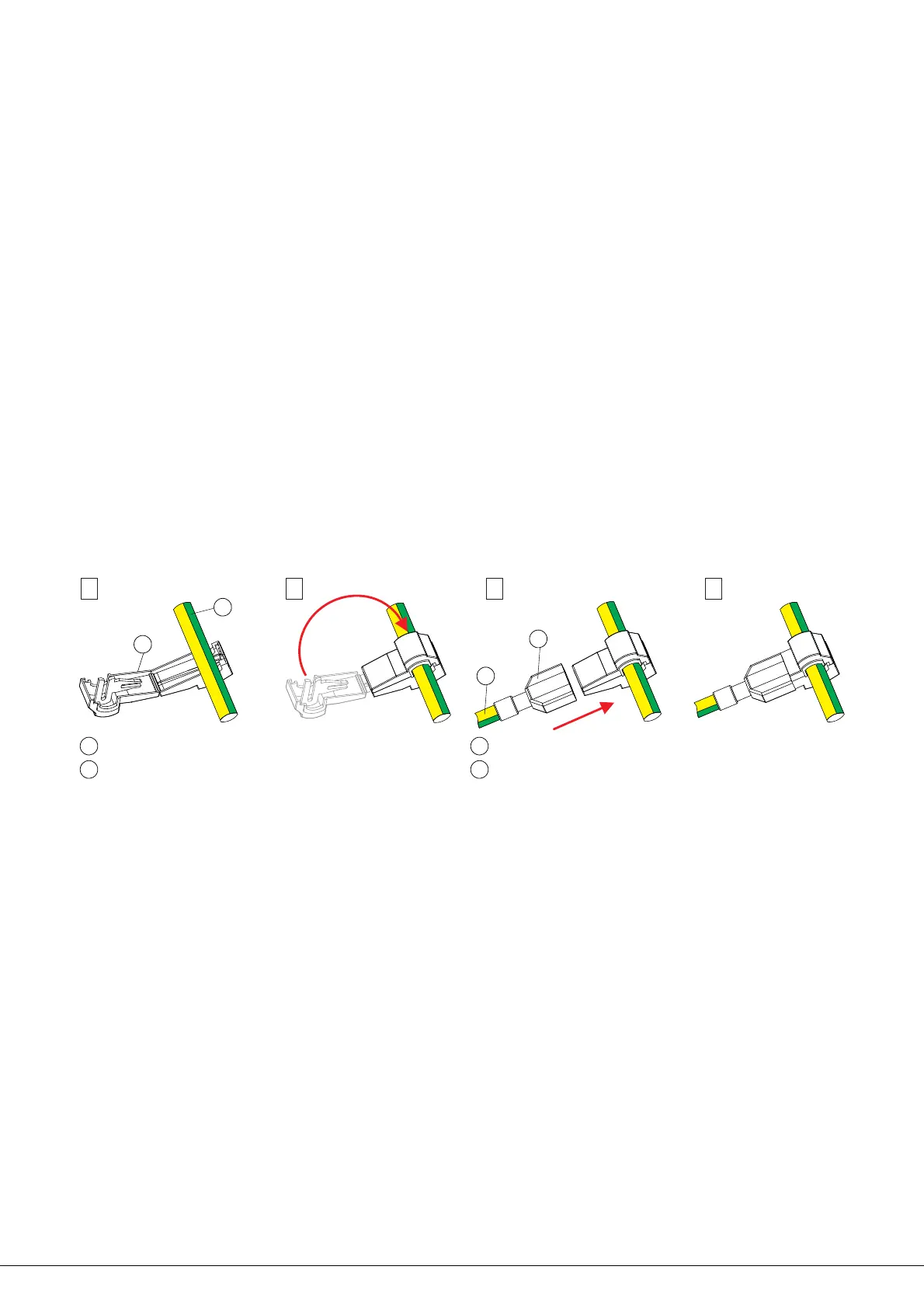
Connection of the protective conductors is recommended to be carried out by means of a t-tap nylon insulated female
terminal and mating red nylon insulated male tab (for wires with cross-section from 0.5 to 1.5mm ). The male tab is
fastened to the protective conductor of the commutator by crimping. The procedure of connecting the protective
conductors is shown on Figure 4.
The t-tap nylon insulated female terminal and nylon insulated male tab are not supplied with the device. These parts
are available upon request.
Figure Connection of protective conductors
Put the device cover back on its place.
().
).
4 -
EXAMPLE OF WIRING DIAGRAMS
EXAMPLE OF CONFIGURATION
DIAGRAM EXAMPLE OF WIRING DIAGRAMS
2
use cables with copper wires.
The main video line from the doorstation to the device shall be coaxial cable RG-59 or similar, which has a copper
central core and copper-wire braid. Cables with an iron central core and aluminum foil braiding are not recommended.
Connect conductors of those BK-4AV devices which have
www.vizit-group.com BK-4AV Operating Instruction (revision 6 12 3201 - ) /6
1 2 3 4
2
1
1
T-tap female terminal
2
Trunk protective conductor
3
4
3
Insulated male tab
4
Protective conductor of the commutator
 Loading...