【
BEGIN TO USE THE NEW ESC】
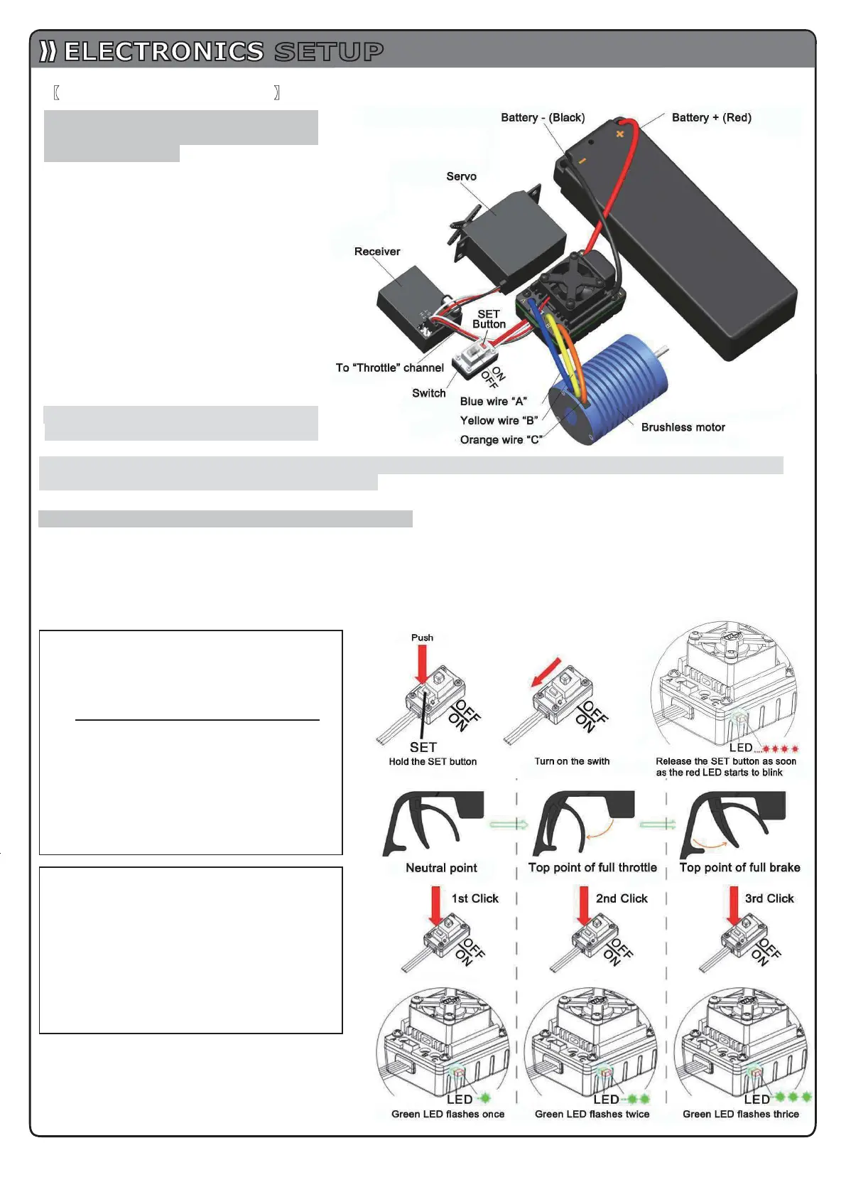
1. Connect the ESC, motor, receiver,
battery and servo according to the
following diagram
“+” and “-” wires of the ESC are
connected with the battery pack, and #A,
#B and #C are connected with the motor
wires. The “SET” button is used for
programming the ESC.
The control cable of the ESC (trio wires
with black, red and white color) is
connected with the throttle channel of the
receiver (Usually CH2).
1The #A, #B, #C wires of the ESC can be
connected with the motor wires freely
(without any order). If the motor runs in
the opposite direction, please swap any
two wire connections.
Note: You can use the transmitter to
set the throttle channel to
the“Reverse” direction, and then the motor will run oppositely. Please calibrate the throttle range again
after changing the direction of throttle channel.
2. Throttle Range Setting (Throttle Range Calibration)
In order to make the ESC match the throttle range, you must calibrate it when you begin to use a new ESC, or a
new transmitter, or after changing the settings of the neutral position of throttle channel, ATV or EPA parameters,
otherwise the ESC cannot work properly.
There are 3 points need to be set, they are the top point of
“fo
rward”,”
backward”
and the neutral point.
The following pictures show how to set the throttle range with a Futaba
TM
transmitter.
Note2: If you don’t release the “SET” key after the
red LED begins to flash, the ESC will enter the
program
mode, in such a case, please switch off
the ESC and re-calibrate the throttle range again
from step A to step D.
A) Switch off the ESC, turn on the
transmitter, set the direction of throttle
channel to ”REV”, set the “EPA/ATV
”
value of throttle channel to “100%”, and
disable the “ABS” brake function
of
your transmitter.
(
*Note2)
B) Hold the “SET” key and then switch on
the ESC, when the red LED begins to
flash, release the key immediately.
(Please check the picture on the right side)
C) Set the THREE points according to the
steps shown in the picture on the right
side.
1) Neutral point
2) End point of forward direction
3) End point of backward direction
D) When the process of calibration is
finished, the motor can be started after
3 seconds.
SETUP
6