4 Assembly and Operations Manual EXTRA - 330L SEMI SCALE SPORT MODEL
CHECK OFF TOOLS AND SHOP MATERIALS NEEDED.
These tools and shop materials are not included and are
required to complete and operate your EXTRA - 330L and
most other remote control aircraft. For some specific
recommendations and part numbers please see the
attached listing of tools and materials available in your
market area.
- Clean and flat table or work surface approximately
600 x 1800 mm (24 x 72 in)
- 2.5 mm ball socket screw driver or Allen wrench
- 3.0 mm ball socket screw driver or Allen wrench
- 4.0 mm ball socket screw driver or Allen wrench
- Phillips (cross head) screw driver small size
- Phillips (cross head) screw driver medium size
- Flat blade screw diver medium size
- Low tack masking tape, ruler or tape measure
- Side (“wire”) cutters
- Pencil, pliers, hobby knife with #11 blade
- 30 minute Epoxy and 240 grit sandpaper
- Silicon Based Sealant (Dap – A – Goo)
- Epoxy mixing dishes, brushes and sticks
- Paper towels
- Rubbing alcohol
- Crescent wrench (optional)
- Heat gun and heat iron for covering
(optional for covering touch up)
CHECK OFF OTHER ITEMS NEEDED TO COMPLETE EXTRA-330L SEMI SCALE SPORT MODEL
- These items are not included and are required to
complete and operate your VMAR MODEL and most
other remote control aircraft.
- Medium fuel tubing appropriate for your choice of
engine and fuel. 500 – 750 mm ( 24-36 in.)
- Liquid thread locker
- RC FM radio with at least four channels of control and
on a frequency appropriate for your market area.
- Five servos compatible with the RC FM Radio.
Servos generally are sold with new radio systems
- External Switch Actuator appropriate for your radio
system (optional)
- Engine and muffler suitable for use in a remote control
model aircraft. A two stroke glow fuel .40 - .53 cubic
inch engine is recommended.
- Propeller suitable for the engine. See the engine
instruction manual recommendation for diameter and
pitch.
- Engine glow plug
- Engine glow plug igniter
- Engine 4 way wrench
- Fuel for the engine
- “After run” oil for engine
- RC Foam sheeting for wrapping radio receiver
and battery pack.
CHECK OFF OPTIONAL EQUIPMENT AND ACCESSORIES.
- These items are not included and are not required but
make the operation of your EXTRA - 330L and most
other remote control aircraft easier & more enjoyable.
- Power Tote Deluxe field box # VMA-PT109D
- Fuel pump and connecting tubing
- Fueling valve
- Chicken stick or electric starter
- Stick on weights
- Battery to power electric starter
- Battery charger
- Power Panel to manage starter and pump if electric.
- Extra propellers
- Extra Glow Plugs
- Misc Tools
- Engine test stand # VMA – ETS120
Assembly and Operations Manual EXTRA - 330L SEMI SCALE SPORT MODEL 13
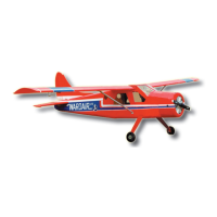
Install the rubber servo grommets and brass ferrules
supplied with your radio equipment. The three servos that
control the elevator, rudder and throttle are Installed in the
servo tray mounted in the fuselage. Remove the servo
tray from the fuselage and mount the servos to the servo
tray as shown.
17.A Universal servo tray.
18.A Position of throttle, rudder and
elevator servos and connected
to the pushrods.
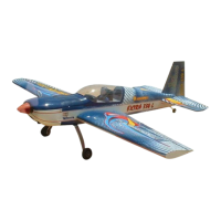
Connect the elevator servo to the receiver and turn on
your transmitter. Confirm that the neutral positions of the
elevator servo are sustained.
INSTALLING THE SERVOS
Stage 17
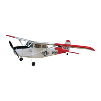
CONNECTING THE PUSHRODS TO THE THROTTLE, RUDDER AND ELEVATOR SERVOS
Stage 18
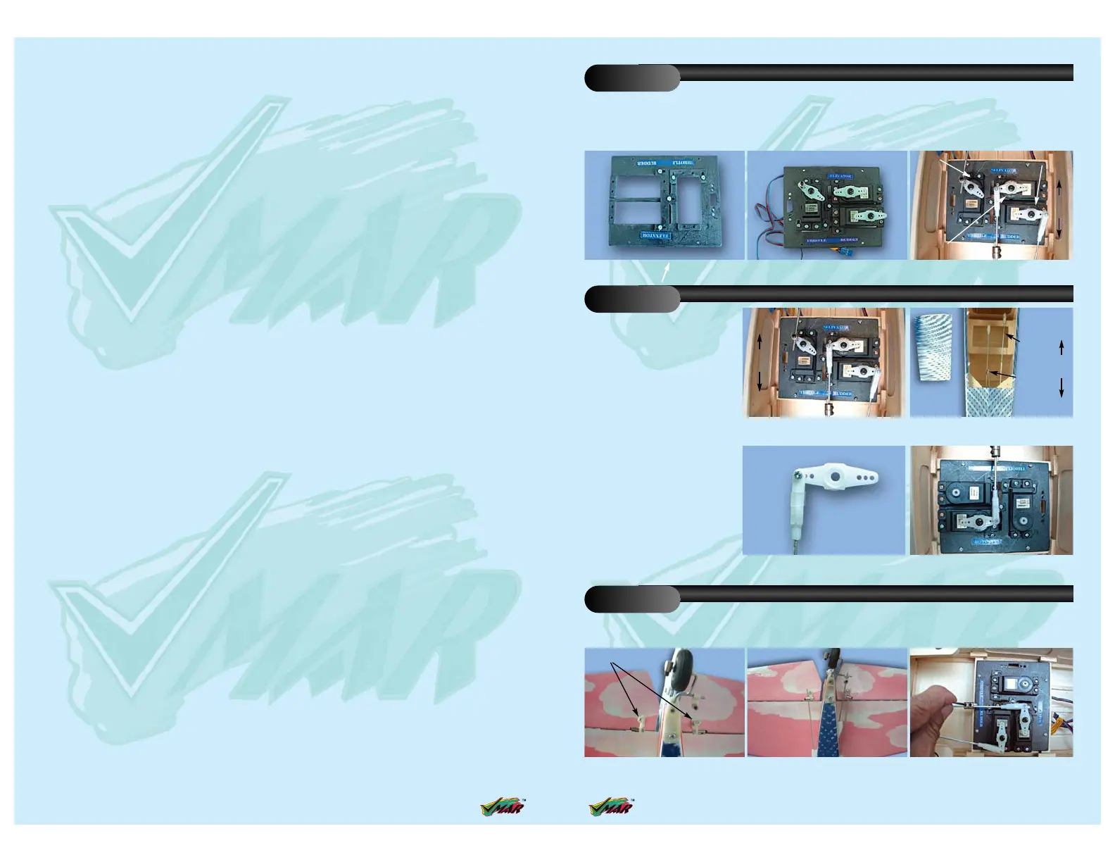
CONNECTING THE PUSHRODS TO THE ELEVATOR
Stage 19
17.C Throttle, elevator and rudder servos
connected to their repective push rod.
17.B Note the orientation and positions
of the three servos in the servo tray.
18.B Pre-installed elevator and
rudder pushrod
18.D Connecting the elevator pushrod
to the elevator servo arm
18.C Connecting clevise to the servo arm
19.A Two independent elevator control
horns shown in position
19.C Loosen collars to align elevator
surfaces. Tighten collars securely
19.B Connecting the elevator pushrods
to the control horns
Elevator control
horn
Consult the pictures showing how
the throttle, rudder and elevator
servos are positioned and connect-
ed to the pushrods.
Throttle servo
Throttle servo
Rudder servo
Rudder servo
Elevator servo
Elevator servo
Front
Rear
Elevator
control rod
Rudder
control rod
Front
Rear
Rear
Front
Rear
 Loading...