EasyManua.ls Logo

Vmar EXTRA-330L User Manual

Vmar EXTRA-330L
8 pages
To Next Page IconTo Next Page
Page #1 background imageLoading...
Page #1 background image
EXTRA - 330L
SEMI SCALE SPORT MODEL
Assembly
and
Operations Manual
Please review this manual throughly
Before assembling or Operating
The
VMAR EXTRA - 330L
Semi scale sport model
EXTRA - 330
We’ve used our ULTRA TOUGH POLYCOTE ECS Enhanced Covering System for this Model
16 Assembly and Operations Manual EXTRA - 330L SEMI SCALE SPORT MODEL
1/3"
8.5 mm
1/3"
8.5 mm
1/4"
6.35 mm
1/4"
6.35 mm
5/8"
16 mm
5/8"
16 mm
Elevator Aileron Rudder
NOTE : The throws are measured at the widest part of the elevator, rudder and aileron. Adjust the position of the pushrods
at the control/servo horns to control the amount of throw. You may also use the ATV’s if your transmitter has them but the
mechanical linkages should still be set so that the ATV’s are near 100% for best servo resolution.
High rate Low rate
ELEVATOR 1/2” (12.6 mm) up 1/3” (8.5 mm) up
1/2” (12.6 mm) down 1/3” (8.5 mm) down
RUDDER 1” (25.4 mm) right 5/8” (16 mm) right
1” (25.4 mm) left 5/8” (16 mm) left
AILERON 3/8” (9.5 mm) up 1/4” (6.35 mm) up
3/8” (9.5 mm) down 1/4” (6.35mm) down.
Note: If your radio does not have dual rates, then set the control surfaces to move al the low rate throws.
Note
Question and Answer IconNeed help?

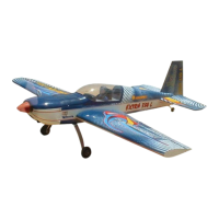
Do you have a question about the Vmar EXTRA-330L and is the answer not in the manual?

Vmar EXTRA-330L Specifications

General IconGeneral
BrandVmar
ModelEXTRA-330L
CategoryToy
LanguageEnglish

Summary

EXTRA - 330L SEMI SCALE SPORT MODEL

Control Surface Throws

Specifies high and low rate throws for elevator, rudder, and aileron control surfaces.

Installing the Receiver Battery

Installing the Receiver

Confirm Radio Operation

Radio System Testing

Consult radio manual for testing and operating procedures, including battery charging and range checks.

Balancing the Aircraft (CG)

CG Location and Measurement

CG is located 120-130mm from the wing's leading edge, measured without fuel.

Adjusting Center of Gravity

Adjust CG by moving components, changing engines, or adding weight.

Confirm Mechanical Integrity

Pre-Flight Inspection

Thoroughly review all model components and connections before the first flight.

Third-Party Check

Have an experienced flyer check your work before the first flight.

Connecting Pushrods and Controls

Adjust Control Surface Throw

Adjust control surface deflection using clevis or horn position for desired throw limits.

Final R/C Set-up

Installing Servos and Controls

Install Aileron Servos

Fit servos into wing cavities, connect wires, and install control horns.

Connect Pushrods to Servos

Connect throttle, rudder, and elevator servos to their respective pushrods.

Wing Installation and Control Horns

Install Plug-In Wing

Install wing spar joiners and slide wing panels onto fuselage spars.

Fit Elevator and Rudder Control Horns

Install control horns on the underside of elevator halves and rudder.

Fitting Aileron Servos and Tail Wheel

Fuel Tank and Engine Installation

Install Engine

Mount the engine and fuel tank onto the power module.

Stabilizer Installation

Related product manuals