Assembly and Operations Manual EXTRA - 330L SEMI SCALE SPORT MODEL 7
Step 3
Ensure that the aileron control horns are screwed onto the threaded aileron
control horn bolts and that both control horns are in approximately the same
place on their respective bolts.
Step 4
Connect the aileron servo rods to the aileron control horns. If one of the two
clevises on each rod has a metal pin or screw, attach that clevis to the servo
output arm.
Step 5
Connect the other clevis to the servo output arm
Step 6
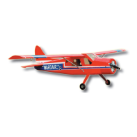
Remove the masking tape holding the ailerons.
Step 7
In the case of computer radios couple the servos together by connecting
them to the appropiate receiver channel. In the case of analog radios
couple the servos together using a Y harness.
Step 8
Turn on your radio and activate the ailerons, using the aileron stick and
ensure a smooth full motion can be achieved.
Step 9
With the wing top side up and viewed from the back, ensure that moving the
transmitter aileron stick to the left raises the left aileron and lowers the right
aileron. Movement of the stick to the left will roll the aircraft to the left.
(Counterclockwise roll of the wing when viewed from the back ).
Step 10
With the wing top side up and viewed from the back, ensure that moving the
transmitter aileron stick to the right raises the right aileron and lowers the left
aileron. Movement of the stick to the right will roll the aircraft to the right.
To install the stabilizer to the fuselage you will need.
- Fuselage
- Vertical stabilizer with pre-installed rudder
- Horizontal stabilizer with pre-installed elevator
3.A Aileron control rod assembly
3.B Aileron control horn assembly
3.C Aileron control installed
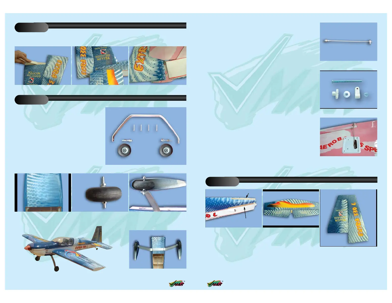
FITTING THE HORIZONTAL AND VERTICAL STABILIZERS
Stage 4
4.A The completed fuselage slot should
look like this
4.C Vertical stabilizers with pre-installed
rudder
4.B Horizontal stabilizers with
pre-installed elevator
Vertical slot
Horizontal slot
10 Assembly and Operations Manual EXTRA - 330L SEMI SCALE SPORT MODEL
Apply sufficient epoxy to both sides and the bottom of
the vertical stabilizer. Use 30 minute epoxy to ensure a
strong bond and give yourself plenty of working time.
Insert the vertical stabilizer in its slot in the fuselage
and re-check the alignment. Excess adhesive should
be cleaned off with a rag or tissue before it cures.
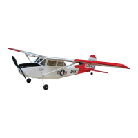
Identify the main landing gear components shown below
- 1 fiberglass main landing gear
- 2 axle assembly
- 2 main wheels ( 60mm x 20mm)
- 2 wheels pants
- 1 Landing gear cover
- 4 sheet metal screws 5 x 35 mm with washers
- 1 tail wheel assembly with 2 (3 x 15mm) sheet metal
screws.
12.A Main landing gear components
FITTING VERTICAL STABILIZER
Stage 11
FITTING THE MAIN LANDING GEAR
Stage 12
11.C Insert the pre-installed hinge to the
rudder
11.B Slide the fin in place11.A Apply plenty of epoxy
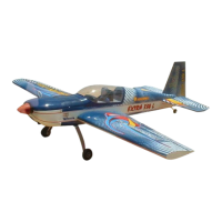
12.D Install the wheel pant and wheel to
the main landing gear
12.C Install the axle and wheel12.B Turn over the fuselage to located
the 4 pre-drilled main landing gear
mounting holes
12.E Use 4 metal sheet screws (5 x 35mm)
to mount the main landing gear onto
the fuselage
 Loading...