6 Assembly and Operations Manual EXTRA - 330L SEMI SCALE SPORT MODEL
To install the aileron servos into the wing you will need the following items:
- Servos
- Servo mounting screws and grommets as supplied with servos.
- Servo control arms as supplied with the servos.
- Two aileron control rod assemblies supplied with the kit. The
assemblies consist of a metal rod with a clevis screwed onto
both ends.
- Low tack masking tape.
- 2 aileron control horn assemblies
Carefully remove the cover plates from the aileron servo cavities. Ensure
you know which cover plate is for the right wing and which is for the left.
Remove the cover plates and retain the mounting screws. Notice that
there are wooden servo rails pre-installed into each servo cavity end. The
tube can be moved slightly at this point. Check out the other end of each
tube for a clean position and then using C/A glue secure the wiring
harness tubes at the aileron servo cavity end.
Install a servo in each aileron servo cavity and connect the servo wire to
the servo extension wires and run the extension wires, install the aileron
control horns.
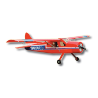
2.A Prepare the servos by fitting the
rubber grommets & ferrules supplied
with your radio
2.B Aileron servo location
Step 1
Consult your radio instruction manual and center each
aileron servos by plugging it into the aileron channel in
the receiver. Turn on the transmitter and then the
receiver. Center the aileron trim lever on the transmit-
ter. Remove the servo arm mounting screw and the
servo arm.
Step 2
Mount the servo arm back on the servo. Position the
arm to be parallel with the back edge of the wing.
Screw the arm into place with the servo arm mounting
screw supplied with the servo.
Locate the two aileron control rods in the hardware
bag. Ensure the clevises are screwed well onto the
threaded portion of the rod. Rotate and tug aggres-
sively on the clevises and ensure that they are not
loose on the rods.
Tape the ailerons into their neutral position so that
they are even with the trailing edge of the wing and
not pointing either up or down.
FITTING AILERON SERVOS
Stage 2
FITTING SERVOS
Stage 3
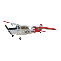
2.C Aileron servo mount 2.D Srew servo into position 2.E Install aileron control horn
Assembly and Operations Manual EXTRA - 330L SEMI SCALE SPORT MODEL 11
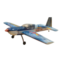
Install the tail wheel assembly. Note that the tail wheel
assembly has a loose wire end. Slide the loose wire end
into the sleeve tube that has been installed into bottom of
the rudder. Position the plastic bracket on the bottom of
the fuselage. Mark the location of the screw holes. Tap
the holes with the screws and then fasten the plastic
bracket to the fuselage. See the illustration below.
To assemble the fuel tank you will need the following items:
- The fuel tank and fuel stopper assembly (supplied)
- The clunk (supplied)
- About 7” (20 cm) of medium ID silicone fuel line
(DUB 197 or similar)
- Cross head Philips screw driver
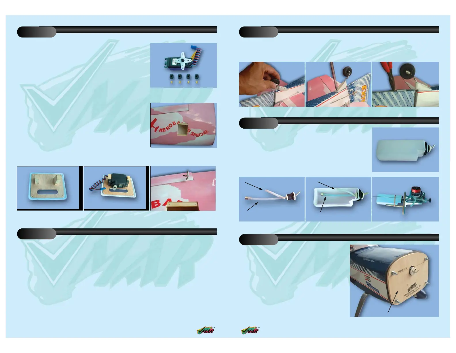
The engine and the fuel tank are installed onto the power
module. First remove the power module from the fuselage by
removing the 4 nuts & washers
FITTING THE TAIL WHEEL
Stage 13
FITTING THE FUEL TANK
Stage 14
13.C Trim off the excess tail steering wire13.B Screw the tail wheel assembly
to the fuselage
13.A Insert the tail wheel steering wire
into the steering guide tube
14.D Fuel tank installed on the
power module
14.C Illustration of fuel line positioning
inside the tank
14.B Use 100 mm (4 in) for fuel line
and 50 mm (2 in) for pressure line
50 mm (2 in.) for pressure line
100 mm (4 in.) for fuel line
Pressure line
Fuel line
INSTALLING THE ENGINE
Stage 15
14.A Fuel tank
Power modul
15.A Power module
 Loading...