Do you have a question about the VOILE Switchback and is the answer not in the manual?
Instructions for installing and re-installing the Hardwire heel assembly.
How to correctly adjust the heel lever and rod length for proper fit.
Procedure to check and adjust forward pressure for optimal flex and retention.
Steps for mounting the Dual LP heel pad using climbing wires.
How to engage and disengage the uphill touring mode latch.
Recommendations for maintenance, screw length, and centering the assembly.
The Voilé Switchback/X2 is a telemark touring binding designed for backcountry and telemark skiing. It is not a safety binding and lacks a release mechanism, meaning it does not reduce the inherent risk of injury associated with the sport. Users are solely responsible for learning proper skiing techniques, avalanche awareness, and exercising good judgment.
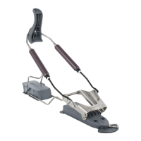
The Switchback/X2 binding facilitates both skiing and uphill touring. It features a toe-plate with a locking mechanism that can be switched between "ski" and "tour" modes. In "tour" mode, the toe-plate disengages, allowing for free pivot for uphill travel. In "ski" mode, the toe-plate locks down, providing a secure connection for downhill skiing. The binding includes a Hardwire heel assembly with adjustable spring cartridges that provide forward pressure and heel retention. Dual LP Climbing Heels with multiple height options (100mm, 80mm, 65mm wires) are integrated to assist with uphill climbs on varying inclines.
The Voilé Switchback/X2 Binding is warranted by the manufacturer against defects in materials and workmanship for a period of one year. Warranty service and replacement parts are available directly through Voilé. The product is Made in Utah, USA.
| Brand | VOILE |
|---|---|
| Model | Switchback |
| Category | Sports & Outdoors |
| Language | English |