Installation and Operating Manual
I/H Converter DSG-B03212
DSG-B07212
J.M. Voith SE & Co. KG │ Division Digital Ventures
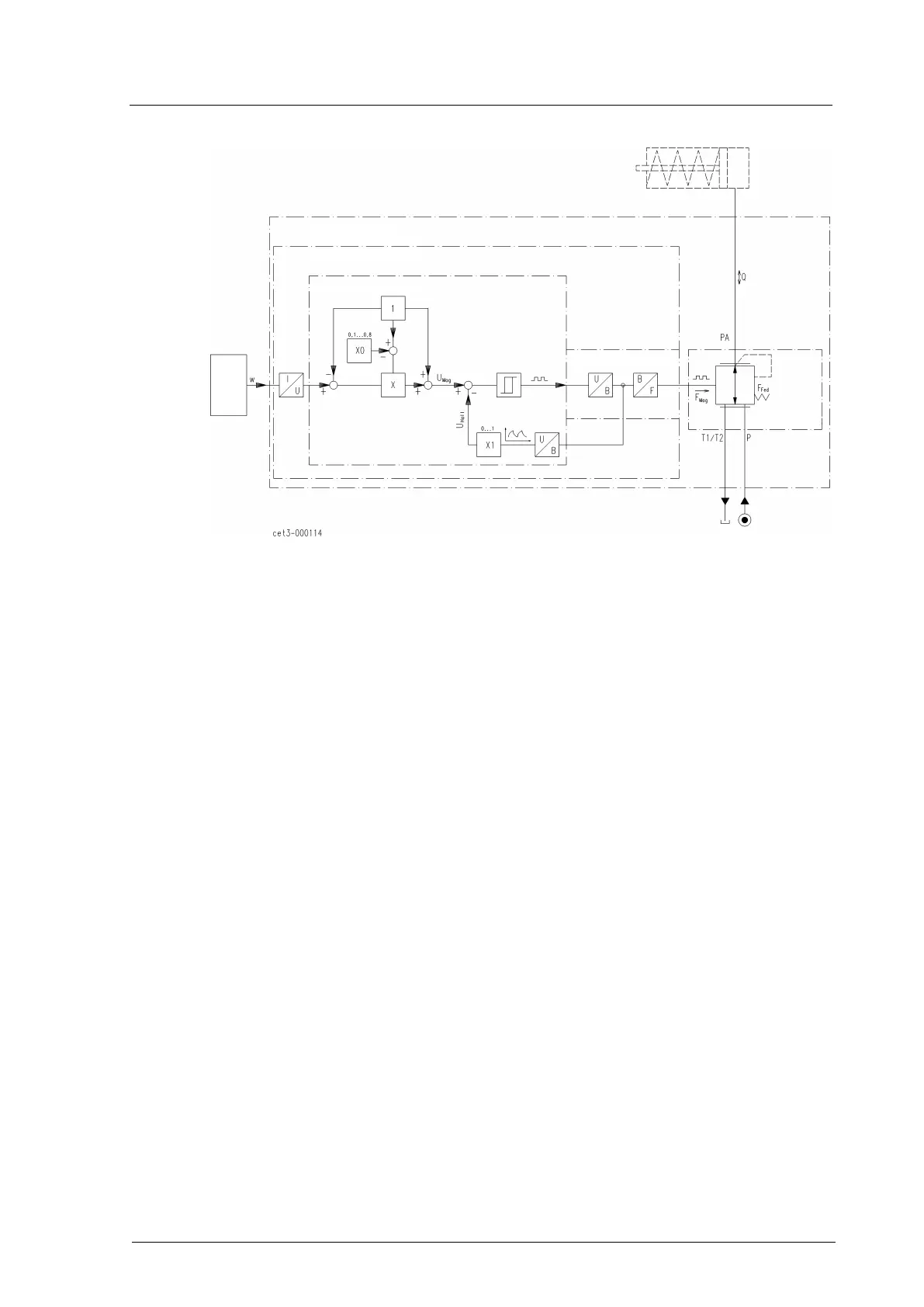
Block diagram - I/H converter
Fig. 2: Block diagram of I/H converter
Pressure control
The control system controls the I/H Converter by an electric signal w = 4…20 mA for the
power setpoint UMag. The actual value in the magnetic system is measured by a Hall
probe and returned to the magnetic force controller as UHall. The magnetic force FMag
assigned to the setpoint w by potentiometers X0 and X1 is transmitted to the control piston
via a tappet. The hydraulic force FHyd being proportional to the output pressure PA acts
against the magnetic force. In balanced condition, the control piston is in center position
and the output pressure PA corresponds to setpoint w.
Spring force FFed of the control spring generates a force offset in order to ensure the I/H
converter function also with output pressures near 0 bar.
Limitation of maximum value
In case of incorrect connection of the setpoint, e.g. by unintentional connection of 24 VDC
to the plus-port of the setpoint input, the setpoint current is limited to an uncritical value by
means of an overload protector integrated in the VRM, thus protecting the I/H converter
control against damage.
Magnetic force controller