2
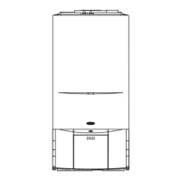
Compact
SECTION 1 DESIGN PRINCIPLES AND OPERATING SEQUENCE
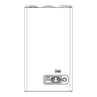
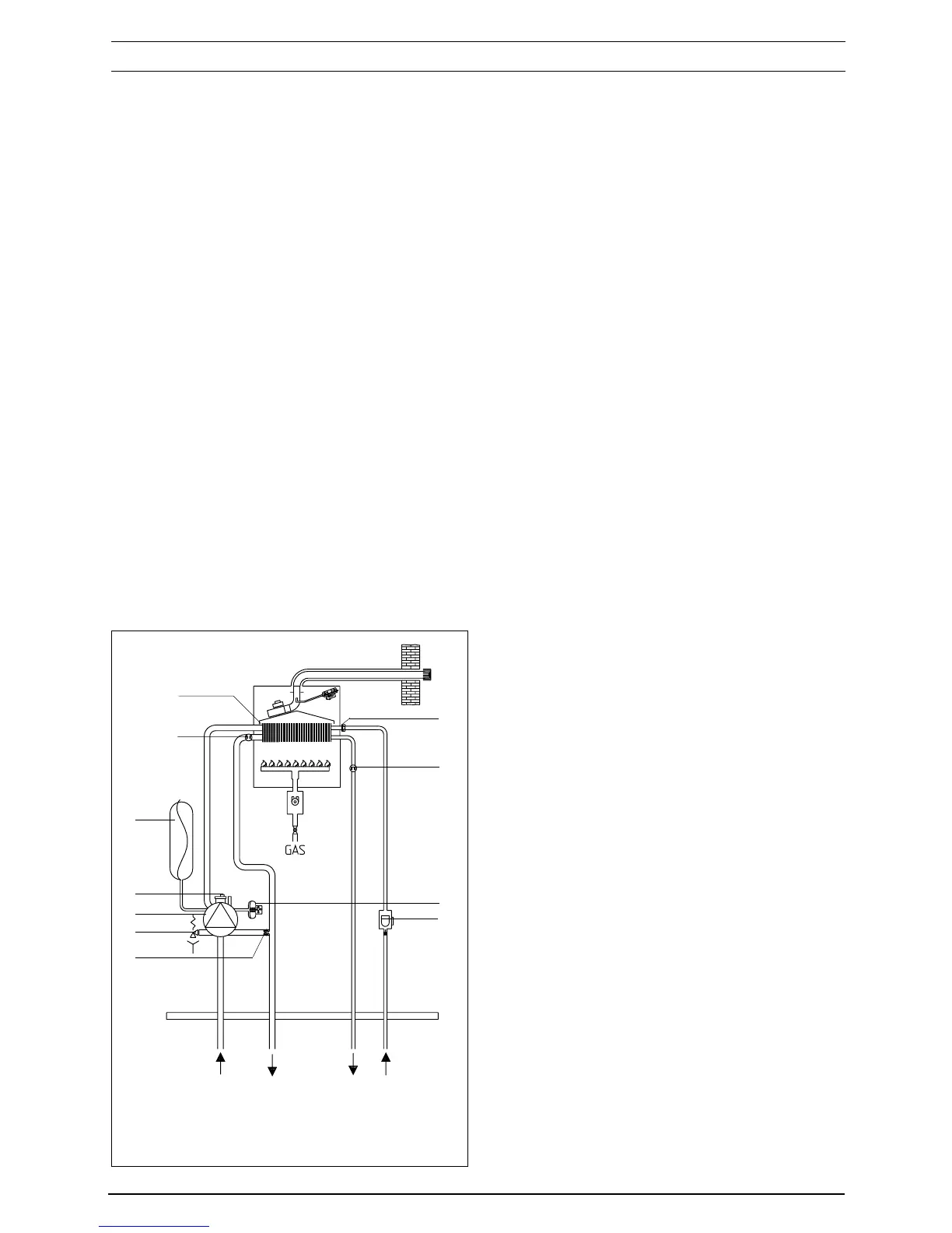
Fig. 2
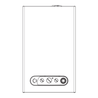
1.1 PRINCIPLE COMPONENTS
● A fully integrated, electronic control board fea-
turing mode selection switch, full sequence-
electronic ignition, temperature control system,
and appliance status indicator.
● A BI-thermal gas to water heat exchanger.
● A multi-functional gas valve.
● Two-stage, primary water pressure switch.
Integral pump, expansion vessel, pressure re-
lief valve, pressure gauge, domestic water flow
switch, fan, differential air pressure switch, and
time clock.
MODES OF OPERATION
1.2 CENTRAL HEATING MODE
When there is a request for central heating via the
time-clock and/or any external controls, the pump
and fan are started, the fan proves the differential
air pressure switch which in-turn, allows an ignition
sequence to begin.
Ignition is sensed by the electronic circuitry to
ensure flame stability at the burner. Once suc-
cessful ignition has been achieved the appliance
operates al 75% of maximum for a fifteen-minute
period, and thereafter the appliance operates on
maximum output until the desired temperature
setting is reached.
Once the desired temperature is reached, the
burner will modulate to maintain that tempera-
ture, however should the temperature within the
appliance continue to rise, the burner will shut
down and the boiler will perform a three-minute
anti-cycle (timer delay).
1.3 HOT WATER MODE
When there is a demand for domestic hot water
the domestic hot water flow switch is proved by
the flow of water through the appliance, this
allows the fan to run, the fan proves the differen-
tial air pressure switch which in-turn, allows an
ignition sequence to begin.
Ignition is sensed by the electronic circuitry to
ensure flame stability at the burner. Once
successful ignition has been achieved the appli-
ance will modulate burner gas pressure to main-
tain the desired water temperature, should the
temperature of the domestic hot water exceed
the temperature setting by 5 ºC the burner will
shut down until the water temperature drops
below the required setting.
1.4 SAFETY DEVICES
In both central heating and domestic hot water
modes, safe operation is ensured by.
● A water pressure switch that monitors the sys-
tem pressure and will deactivate the pump and
prevent burner ignition should the pressure or
primary flow rate fall below the rated tolerance.
● Differential air pressure switch that checks the
correct operation of the fan and flue thereby
preventing or interrupting burner operation.
● A high limit thermostat that overrides the con-
trol circuit to prevent or interrupt burner ignition.
● A safety valve which releases excess pressure
from the primary circuit.
1.5 FROST PROTECTION
The appliance has built-in frost protection that
allows the pump to operate if the appliance tem-
perature drops to 7 ºC, should the temperature
continue to drop the burner will light until the
primary circuit temperature exceeds 30 ºC.
return flow
hw
outlet
cold
inlet
27
5
9
10
26
19
8
23
4
20
18
 Loading...