Do you have a question about the VOKERA Excel 29 and is the answer not in the manual?
Legal requirement for gas appliance installation and maintenance by competent persons.
Appliance connection to double pole isolator or unswitched socket with correct fuse.
Fill out and post guarantee registration card within 30 days of installation.
Benchmark checklist completion during installation/commissioning is mandatory for warranty.
Explains how the boiler provides heating and hot water using electronic ignition.
Provides height and width specifications for the Excel 25-29 models.
Specifies minimum clearances for above, below, sides, and front of the appliance.
Built-in system to prevent frost damage by operating the burner/pump below 5°C.
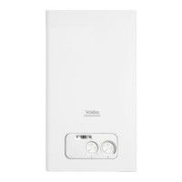
Explains the function of Green, Red, and Yellow LEDs indicating boiler status.
Explains Green, Red, and Yellow LEDs indicating boiler status.
Selector to adjust hot water outlet temperature.
Indicates current system pressure, minimum 0.5-bar.
Controls boiler mode (Hot water only, Heating & Hot water, OFF) and heating temperature.
Familiarize with isolation, pressure check, time clock, thermostats, and controls.
Instructions for turning on the gas and electrical supply and initiating ignition.
How to adjust the central heating temperature using the selector.
How to adjust the hot water temperature using the selector.
Highlights the appliance's advanced technology and simultaneous functions.
Explains the SARA function for automatic heating adjustment.
Step-by-step guide to checking and topping up system water pressure.
Procedure for resetting the appliance when the red fault LED is illuminated.
Advise to turn off the time clock and main water supply.
Recommends draining the system and turning off supplies.
Cleaning instructions using a damp cloth, avoiding abrasive cleaners.
Advice to turn off gas supply and contact installer or supplier.
Suggests contacting installer to inspect for leaks if frequent topping-up is needed.
Advice for tenants to arrange servicing with their landlord.
Guidance on contacting installer or Vokèra with necessary details.
Instructions for setting the time and switching times on the mechanical clock.
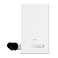
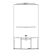
Labels and identifies key components of the appliance's general layout.
Lists the key electronic and mechanical components of the appliance.
Describes functions active when the appliance is idle, including frost protection.
Explains the sequence of operation for central heating requests.
Explains the sequence of operation for domestic hot water requests.
Details the various safety features integrated into the appliance.
Provides technical specifications for central heating performance.
Provides technical specifications for domestic hot water performance.
Lists gas pressure parameters for the appliance.
Details the capacity and pre-charge pressure of the expansion vessel.
Provides physical dimensions and weight of the appliance.
Specifies required clearances for installation.
Lists connection types and sizes for gas, water, and flue.
Details electrical specifications like power consumption and fuse ratings.
Provides flue length limitations for concentric 60/100mm flue systems.
Provides flue length limitations for concentric 80/125mm flue systems.
Provides flue length limitations for twin pipe flue systems.
Details the efficiency ratings of the appliance.
Lists emission data such as CO2, CO, and NOx ratings.
Explains the pump duty graph and its use for system requirements.
Lists relevant British Standards and regulations for installation.
Guidance on suitable and unsuitable locations for appliance installation.
Requirements for gas meter and pipework sizing and testing.
Guidance on terminal location, condensate, and protection guards.
Notes that the appliance is room-sealed and requires no permanent air vent.
Recommendations for pipework, gradients, insulation, and avoiding freezing.
Recommendations for copper tubing, capillary joints, and pipe gradients.
States the appliance has a built-in by-pass, no external one needed.
Requirement for accessible drain cock locations.
Importance of positioning air release points correctly.
Notes the integral expansion vessel and potential need for additional capacity.
Details the method for initial filling and replacement water.
Describes an alternative filling method from a make-up vessel.
Frequent filling may indicate a leak; system must withstand 3 bar.
Details 230V/50Hz supply, 3-amp fuse, and preferred connection methods.
No requirement to protect the wall when mounting on combustible material.
Guidance for installation in timber framed buildings.
Recommendation to use an inhibitor suitable for aluminium heat exchangers.
Requirement for thermostatically controlled showers.
Lists relevant Irish regulations for installation.
Guidance on appliance location and compartment design in Ireland.
Requirements for gas meter and pipework sizing in Ireland.
Guidance on flue terminal location and protection in Ireland.
Notes that the appliance is room-sealed, requiring no permanent air vent in Ireland.
Recommendations for pipework, insulation, and avoiding freezing in Ireland.
Recommendations for copper tubing and pipe gradients in Ireland.
States the appliance has a built-in by-pass, no external one needed in Ireland.
Requirement for accessible drain cock locations in Ireland.
Importance of positioning air release points correctly in Ireland.
Notes the integral expansion vessel and potential need for additional capacity in Ireland.
Details the method for initial filling and replacement water in Ireland.
Describes an alternative filling method from a make-up vessel in Ireland.
Frequent filling may indicate a leak; system must withstand 3 bar in Ireland.
Details 230V/50Hz supply, 3-amp fuse, and preferred connection methods in Ireland.
No requirement to protect the wall when mounting on combustible material in Ireland.
Guidance for installation in timber framed buildings in Ireland.
Recommendation to use an inhibitor suitable for aluminium heat exchangers in Ireland.
Requirement for thermostatically controlled showers in Ireland.
Requirement for a Declaration of Conformity to be provided upon installation.
Guidance on handling and unpacking the appliance carton.
Lists items included in the appliance packaging.
Instructions for safely unpacking the appliance and accessories.
Advice on selecting a suitable mounting surface and marking positions.
General guidance on flue applications (horizontal, vertical, twin flue).
Instructions for fitting the 60/100mm concentric horizontal flue system.
Instructions for fitting the 60/100mm concentric vertical flue system.
Guidance on extending flue runs, including bends and condensate drainage.
Instructions for connecting the safety valve discharge pipe.
Guidance on connecting the condensate outlet pipe to a waste system.
Connecting the flexible condensate pipe to the trap and waste.
Details on connecting the appliance to the electrical supply.
Step-by-step guide to removing the appliance casing.
Location of the terminal block on the rear of the control fascia.
Instructions for connecting the 230V mains input cable to the terminal block.
Instructions for connecting the gas supply pipe to the service valve.
Instructions for connecting flow and return pipes to service valves.
Instructions for connecting the cold water inlet using a stopcock.
Instructions for connecting the hot water outlet pipe.
Instructions for connecting the safety valve discharge pipe.
Guidance on connecting the condensate outlet pipe to a waste system.
Connecting the flexible condensate pipe to the trap and waste.
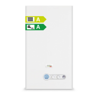
| ERP Rating | A |
|---|---|
| Boiler Type | Combination |
| Output (kW) | 29 kW |
| Mounting | Wall Mounted |
| DHW Output (kW) | 29 kW |
| Operating Pressure | 0.5 - 3 bar |