14
IMPORTANT
The vertical ue terminal is 1.0 metre in length and cannot be
cut; therefore it may be necessary to adjust the height of the
appliance to suit or use a suitable extension.
Connect the vertical ue assembly to the boiler ue spigot us-
ing the 100mm clip, gasket & screws (supplied), ensuring the
correct seal is made. The ue support bracket (supplied with
the vertical ue kit) can now be tted.
If the vertical ue requires extension/s or additional bend/s,
connect the required number of ue extensions or bends (up
to the maximum equivalent ue length) between the boiler and
vertical ue assembly (see g. 14).
Ensure that any horizontal sections of the ue system have a
minimum 1º; maximum 3º fall back to the boiler (1º = 17mm
per 1000mm).
NOTE
When cutting an extension to the required length, you must
ensure that the excess is cut from the plain end of the exten-
sion. Remove any burrs, and check that any seals are located
properly.
You must ensure that the entire ue system is properly sup-
ported and connected.
4.5.3 TWIN FLUE SYSTEM
The Vokèra twin ue system enables greater ue distances
to be achieved than that of a concentric ue system. It can be
used for horizontal or vertical applications, however the twin
ue system must be converted to the dedicated concentric
ue kit for termination. It is essential that the installation of the
twin ue system be carried out in strict accordance with these
instructions.
GUIDANCE NOTES ON TWIN FLUE INSTALLATION
• The ue must have a have a minimum 1º; maximum 3º (1º =
17mm per 1000mm) fall back to the appliance to allow any
condensate that may form in the ue system to drain via the
condensate drain. Consideration must also be given to the fact
that there is the possibility of a small amount of condensate
dripping from the terminal.
• Ensure that the entire ue system is adequately supported,
use at least one bracket for each extension.
• The entire ue system must be adequately insulated to
maintain heat within the ue system thereby reducing the
possibility of condensate production.
• As the exhaust outlet pipe can reach very high temperatures
it must be protected to prevent persons touching the hot
surface.
• The condensate drain pipe must be connected in accordance
with building regulations.
Reduction for bends
Twin ue accessories
Part No. Description Length
0225805 Horizontal ue terminal 1.0 metre
0225810 Vertical ue terminal 1.0 metre
359 Twin adapter kit N/A
531 Pitched roof ashing plate N/A
532 Flat roof ashing plate N/A
0225815 Condensate drain kit N/A
0225820 0.25m extension (pair) 250mm
0225825 0.5m extension (pair) 500mm
0225830 1.0m extension (pair) 1000mm
0225835 2.0m extension (pair) 2000mm
0225840 45º bend (pair) N/A
0225845 90º bend (pair) N/A
0225850 Twin bracket (5) N/A
0225855 Single bracket (5) N/A
MOUNTING THE BOILER
The xing holes for the wall-mounting bracket should now be
drilled and plugged, an appropriate type and quantity of xing
should be used to ensure that the bracket is mounted securely.
Fig. 13a
HORIZONTAL TERMINATION (g. 13c)
The twin ue system must be converted to the dedicated con-
centric ue kit for termination.
• The horizontal terminal is supplied with a built-in converter
box and cannot be shortened.
• A 130mm hole is required for the passage of the concentric
terminal through the wall.
• The air inlet pipe must always be level with or below, that of
the exhaust pipe.
Depending on site conditions it may be preferable to install the
terminal assembly prior to tting the twin ue pipes.
Mark and drill a level 130mm hole for the passage of the horizontal
ue terminal. Insert the terminal assembly into the ue hole.
Push-t the twin ue pipes onto the concentric to twin converter
box ensuring that the exhaust pipe connects to the exhaust
connection on the concentric to twin converter.
If necessary cut the plain ends (male) of the twin ue pipes to
allow connection to the concentric to twin converter.
NOTE
Before cutting twin ue pipes ensure allowances have been
made for connection onto the previous piece and onto the con-
centric to twin converter. The last twin ue pipes must be pushed
50mm onto the male spigots of the concentric to twin converter.
NOTE
Seal the ue terminal assembly to the wall using cement or a
suitable alternative that will provide satisfactory weatherproof-
ing. The interior and exterior trim can now be tted.
VERTICAL TERMINATION (g. 14)
The twin ue system must be converted to the dedicated con-
centric ue kit for termination.
• The vertical terminal is supplied with a built-in converter box
and cannot be shortened.
Once the bracket has been secured to the wall, mount the ap-
pliance onto the bracket.
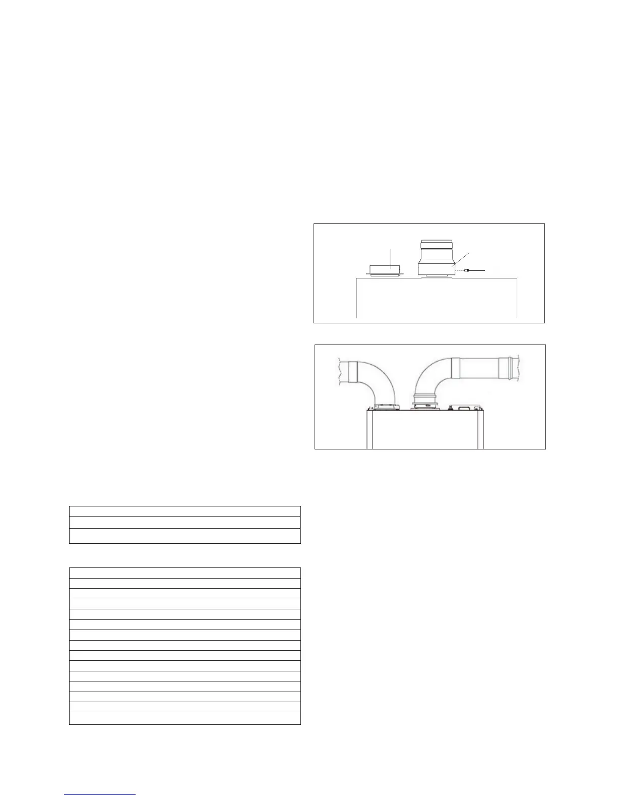
INSTALLATION OF TWIN ADAPTOR KIT (g. 13a-13b)
• Insert the exhaust connection manifold (A) onto the appliance
ue outlet.
• Remove the blanking plate (located to the left of the appliance
ue outlet) and – using the same screws – install the air inlet
plate (B).
• Using the hole in the exhaust connection manifold as a guide,
drill a 3mm hole in the appliance ue spigot and secure the
exhaust manifold connection to the ue spigot using the screw
provided (C).
• Using the two holes in the air inlet plate as a guide, drill a
3mm hole in each and secure the air inlet pipe/bend using
the screws provided.
The twin ue pipes extensions and accessories can now be
installed by pushing together (the plain end of each extension
or bend should be pushed approximately 50mm into the female
socket of the previous piece).
B
A
C
Bend Reduction in maximum ue length for each bend
45º bend 1.0 metre
90º bend 1.5 metre
Fig. 13b