13
Fig.12a
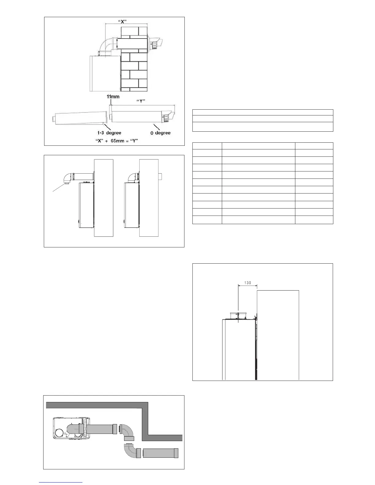
EXTENDING THE FLUE
Connect the bend – supplied with the terminal kit – to the top
of the boiler using clamp (supplied) see g. 11. The additional
bends & extensions have push-t connections, care should be
taken to ensure that the correct seal is made when assembling
the ue system. Connect the required number of ue exten-
sions or bends (up to the maximum equivalent ue length) to
the ue terminal (see g. 11-14). The ue system should have
a minimum of 1º; maximum of 3º rise from the boiler to outside,
to ensure any condense uid that forms, is allowed to drain
back to the appliance.
NOTE
When cutting an extension to the required length, you must
ensure that the excess is cut from the plain end of the extension
(see g. 11-14). Remove any burrs, and check that all seals are
located properly. You must ensure that the entire ue system is
properly supported and connected. Seal the ue assembly to
the wall using cement or a suitable alternative that will provide
satisfactory weatherproong. The interior and exterior trim can
now be tted.
4.5.2 CONCENTRIC VERTICAL FLUE
The appliance can be used with either the Vokèra condensing
60/100mm concentric ue system or the optional 80/125mm
concentric ue system.
NOTE
These instructions relate only to the Vokèra condensing
60/100mm concentric ue system. For specic details on the
installation of the 80/125mm concentric ue system please refer
to the instructions supplied.
The vertical ue terminal can be connected directly to the ap-
pliance ue outlet. Alternatively, an extension or bend can be
connected to the appliance ue outlet if desired, however if
additional bends are tted, a reduction must be made to the
maximum ue length (see table below).
Reduction for bends
Bend Reduction in maximum ue length for each bend
45º bend 1.0 metre (60/100) - 1.0 metre (80/125)
90º bend 1.0 metre (60/100) - 1.5 metre (80/125)
Vertical ue terminal and accessories
Part No. Description Length
29450122 Vertical ue terminal 1000mm
531 Pitched roof ashing plate N/A
532 Flat roof ashing plate N/A
29450123 90-degree bend N/A
29450124 45-degree bends (pair) N/A
29450125 500mm extension 500mm
29450126 1000mm extension 1000mm
29450127 2000mm extension 2000mm
29450128 Telescopic extension 372/519mm
529 Wall bracket pack (5) 208mm
Using the dimensions given in g. 12 as a reference, mark and
cut a 125mm hole in the ceiling and/or roof.
Fig. 12b
Fig. 12c
Fit the appropriate ashing plate to the roof and insert the ver-
tical ue terminal through the ashing plate from the outside,
ensuring that the collar on the ue terminal ts over the ashing.
The xing holes for the wall-mounting bracket should now be
drilled and plugged, an ‘appropriate type and quantity of xing
should be used to ensure that the bracket is mounted securely.
Once the bracket has been secured to the wall, mount the ap-
pliance onto the bracket.
A
Fig. 12