16
4.6.5 SAFETY VALVE (g. 16)
Connect the safety valve connection pipe to the safety valve
outlet. Connect a discharge pipe to the other end of the safety
valve connection pipe and tighten. The discharge pipe must
have a continuous fall away from the appliance to outside and
allow any water to drain away thereby eliminating the possibil-
ity of freezing. The discharge pipe must terminate in a position
where any water – possibly boiling – discharges safely without
causing damage or injury, but is still visible.
4.6.6 CONDENSE PIPE
During normal operation the boiler produces condense which
is collected in a trap located in the lower part of the boiler. A
exible pipe (condense outlet pipe) is connected to the outlet
of the trap. The exible pipe must be connected to a plastic
waste pipe only. The plastic waste pipe must have a minimum
of a 3º fall towards the drain. Any external run of pipe should
be insulated to prevent the risk of freezing.
4.6.7 CONNECTING THE CONDENSATE OUTLET
Connect the exible condense outlet pipe supplied in the carton
to the condense trap inside the boiler, care should be taken to
ensure that the trap connections are not disturbed.
Connect a suitable plastic (not copper) pipe (no less than 20mm
diameter) to the outlet pipe and ensure it discharges in accord-
ance with building regulations or other rules in force.
4.7 ELECTRICAL CONNECTIONS
The boiler is supplied with a 2-metre y-lead. This lead can
be used for connection to the electrical supply. Connect the
y-lead to a fused plug or fused isolator in the following way:
• brown wire to LIVE supply
• blue wire to NEUTRAL supply
• green/yellow to EARTH connection.
Insert the supplied 3-AMP fuse into the fused isolator or fused plug.
Should the y-lead be unsuitable, refer to 4.7.3 for details on
how to connect the electrical supply directly to the boiler.
The electrical supply must be as specied in section 3/3A.
A qualied electrician should connect the appliance to the
electrical supply. If controls - external to the appliance - are
required, a competent person must undertake the design of
any external electrical circuits, please refer to section 8 for
detailed instructions. ANY EXTERNAL CONTROL OR WIRING
MUST BE SERVED FROM THE SAME ISOLATOR AS THAT
OF THE APPLIANCE. The supply cable from the isolator to the
appliance must be 3-core exible sized 0.75mm to BS 6500 or
equivalent. Wiring to the appliance must be rated for operation
in contact with surfaces up to 90 ºC.
4.7.1 CASING REMOVAL (g. 17)
To gain internal access to the appliance you must rst remove
the casing, proceed as outlined below:
• locate and unscrew the 2-screws (A) that secure the outer
casing to the appliance
• lift the casing upward to disengage it from the top locating
hooks and then remove
• store the casing and screws safely until required. Re-t in
the reverse order
• gently lower the control fascia until it rests.
Fig. 16
4.7.2 APPLIANCE TERMINAL BLOCK
The appliance terminal block is located on the rear of the con-
trol fascia. Remove the casing as described in 4.7.1. Gently
pull the control panel forwards and down. Locate the terminal
block cover (g. 18).
NOTE
The appliance comes with a factory tted connector plug to
allow
Quick and easy connection to the Vokera time clock. If it is an-
ticipated that external controls will be required please refer to
the wiring diagrams in section 8 for more detailed information.
4.7.3 CONNECTING THE MAINS (230V) INPUT
Unhook and remove the terminal block cover (230V). Pass the
cable through the cable anchorage point. Connect the supply
cable wires (LIVE, NEUTRAL, & EARTH) to their corresponding
terminals (L, N, & E) on the appliance – high voltage – terminal
block. When connecting the EARTH wire, ensure that it’s left
slightly longer that the others, this will prevent strain on the
EARTH wire should the cable become taut. Do not remove the
link wire unless additional external controls are to be tted (see
section 8). The securing screw on the cable anchorage should
now be tightened. This must be done before the terminal block
cover is re-tted in its position.
NOTE
It is the installer’s responsibility to ensure that the appliance is
properly Earthed. Vokèra Ltd. cannot be held responsible for any
damages or injuries caused as a result of incorrect Earth wiring.
Fig. 17
A
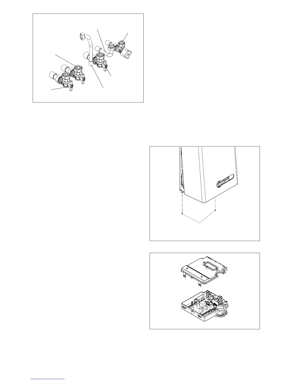
Fig. 18
Hot water
outlet
Cold water inlet
stopcock/lling
valve
Gas
cock
C/H ow
valve
C/H return
valve
Safety
valve outlet