8
2.10 Efciency Excel 25 Excel 29
SEDBUK (%) 90.0 90.2
2.11 Emissions Excel 25 Excel 29
CO2 @ maximum output (%) 9.0 9.0
CO2 @ minimum output (%) 9.5 9.5
CO @ maximum output (ppm) 180 160
CO @ minimum output (ppm) 20 20
NOx rating class 5 class 5
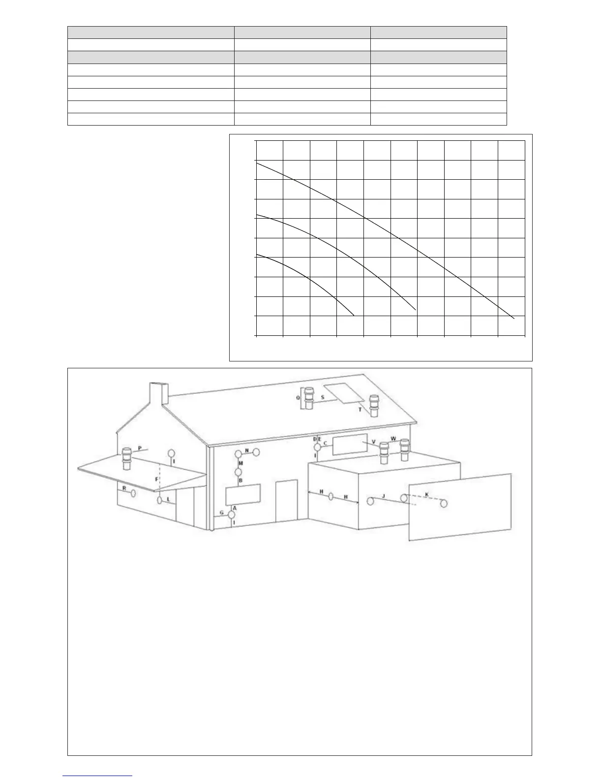
Fig. 6
2.12 PUMP DUTY
Fig. 6 shows the ow-rate available – after
allowing for pressure loss through the ap-
pliance – for system requirements. When
using this graph, apply only the pressure
loss of the system. The graph is based on
a 20
o
C temperature differential.
Fig. 7
Flow rate (l/h)
Residual head (x 100 mbar)
1st speed
2nd speed
3rd speed
Key Location Minimum distance
A Below an opening (window, air-brick, etc.) 300 mm
B Above an opening (window, air-brick, etc.) 300 mm
C To the side of an opening (window, air-brick, etc.) 300 mm
D Below gutter, drain-pipe, etc. 25 mm
E Below eaves 25 mm
F Below balcony, car-port roof, etc. 25 mm
G To the side of a soil/drain-pipe, etc. 25 mm (60mm for 80/125 - 5” ue)
H From internal/external corner 25 mm (60mm for 80/125 - 5” ue)
I Above ground, roof, or balcony level 300 mm
J From a surface or boundary facing the terminal 600 mm
K From a terminal facing a terminal 1200 mm
L From an opening in the car-port into the building 1200 mm
M Vertically from a terminal on the same wall 1500 mm
N Horizontally from a terminal on the same wall 300 mm
P From a structure to the side of the vertical terminal 300 mm
Q From the top of the vertical terminal to the roof ashing As determined by the xed collar
of the vertical terminal
R To the side of a boundary 300 mm
S To the side of an opening or window on a pitched roof 600 mm
T Below an opening or window on a pitched roof 2000 mm
V From a vertical terminal to an adjacent opening (window, air-brick, etc.) (call Vokera technical for advice)
W From a vertical terminal to an adjacent vertical terminal 300 mm (only if both terminals are the same hight)