27
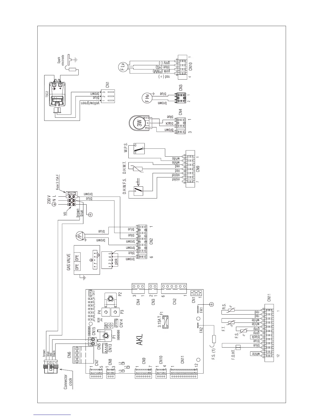
FUNCTIONAL DIAGRAM
Fig. 41
NOTE: L-N-E connection is advisable
AKL Main PCB
P1 Selector switch and heating potentiometer
P2 DHW potentiometer
P3 Unused
P4 Unused
JP1 Unused
JP2 Unused
JP3 Unused
JP4 Unused
JP5 Unused
JP6 Unused
JP7 Unused
JP8 Closed - Unused
LED Led 1 (green) working status or temporary stop
Led 2 (yellow) CO2 function ON
Led 3 (red) boiler lock out
CN1-CN15 Connectors - CN5 Room thermostat (24 Vdc)
S.W. CO2 function button
F.S. (1) Flame sensor
F1 Fuse 3.15A T
F External fuse 3.15A F
M3 Terminal strip for electrical connection hight power
P Pump
OPE Gas valve solenoids
F Hv Fan power supply 230 V
F Lv Fan signal control
D.H.W.F.S Domestic hot water ow switch
D.H.W.T Domestic hot water temperature
WPS Water pressure switch
S.E. Spark electrode
TSC2 Ignition transformer
3W 3 way motor
F.O.H.T Flow over heat thermostat
FS Flue sensor
FT Flow thermistor (NTC)
RS Return thermistor (NTC)