21
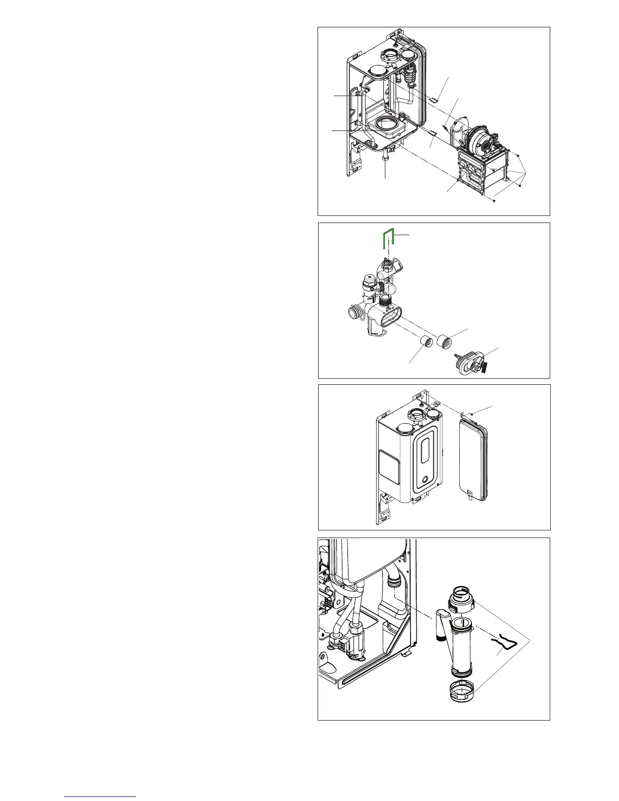
Fig. 29
A1
B1
G1
M1
N1
O1
P1
J1
Fig. 30
Q1
T1
S1
R1
Fig. 32
Fig. 31
W1
V1
U1
6.16 MAIN HEAT EXCHANGER (g. 29)
Carry out component removal procedure as described in 6.4.
Remove the air chamber front cover. Locate and remove the
gas pipe locking pin (A1) and swing/rotate the gas pipe away
from the fan assembly (B1), (if necessary unscrew the gas pipe
from the gas valve G1). Disconnect the electrical connections
attached to the fan. Disconnect the electrode leads and ancillary
wiring from their respective connectors.
Disconnect the ow locking pin (M1), return locking pin (N1)
on the heat exchanger. Locate and remove the 5-screws that
secure the heat exchanger to the combustion chamber (O1).
Move the heat exchanger and disconnect it from the ue collector
(P1). The heat exchanger can now be lifted up and withdrawn
from the appliance.
Replace in the reverse order. Ensure all seals are in good
condition, taking care to ensure they are replaced correctly.
6.17 AUTOMATIC BY-PASS & DHW NON-RETURN
VALVE (g. 30)
Carry out component removal procedure as described in 6.4.
Remove the locking pin (Q1) that secures the cover (R1) to
the hydraulic manifold. Using a hooked piece of wire, carefully
withdraw the by-pass cartridge (S1) and/or DHW non-return
cartridge (T1). Ensure all seals are in good condition, taking
care to ensure they are replaced correctly. Replace in the
reverse order ensuring the cartridge is facing the correct way.
6.18 EXPANSION VESSEL REMOVAL (g. 31)
Carry out component removal procedure as described in 6.4.
Disconnect the expansion vessel from the exible expansion
pipe. Disconnect the exible expansion pipe from the vessel.
Unscrew the nut that secures the vessel to the lower frame.
Locate and remove the screw (U1) that secure the vessel to
the top. The expansion vessel can now be removed. Replace
in the reverse order. Ensure all seals are in good condition,
taking care to ensure they are replaced correctly.
6.19 CONDENSE TRAP REMOVAL (g. 32)
Carry out component removal procedure as described in 6.4.
Disconnect the the locking pin (V1) that secures the trap to
the air condense pipe. Disconnect the lower rubber condense
pipe from the condense trap. Carefully remove the condense
trap. For cleaning unlock the upper and lower closing plug (W1).
Replace in the reverse order.