14
Compact
4.6.2 FLOW & RETURN (fig. 6)
The appliance is supplied with 22 mm service
valves for the heating connections, connect 22 mm
pipe to the inlet of each valve and tighten both nuts.
4.6.3 SAFETY VALVE (fig. 6)
The appliance is supplied with a 15 mm compres-
sion coupling. Connect a 15 mm pipe to the
coupling and tighten. It may be necessary to fit a
non-return valve if the installation is subject to
mains knock, in order to eliminate false activation
of the domestic hot water flow switch.
4.6.4 COLD WATER INLET (fig. 6)
The appliance is supplied with a 15mm stopcock,
connect a 15mm service pipe to the inlet of the
service valve and tighten both nuts. It may be
necessary to fit a pressure reducing valve if the
installation is subject high-pressure fluctuations
or high pressure surges.
4.6.5 HOT WATER OUTLET (fig. 6)
The appliance is supplied with a 15 mm copper
tail, connect a 15 mm pipe and suitable coupling
to the tail and tighten. The discharge pipe must
have a continuos fall away from the boiler to
outside and allow any water to drain away thereby
eliminating the possibility of freezing. The dis-
charge pipe must terminate in a position where
any water – possibly boiling – discharges safely
without causing damage or injury, but is still
visible.
4.7 ELECTRICAL CONNECTIONS
The electrical supply must be as specified in 3.7/
3.7A. the appliance is supplied, pre-wired with a
1.0 metre length of flex, connect the wires as
follows:
● connect the Brown wire to the L (Live) terminal
of the plug or fused isolator
● connect the Blue wire to the N (Neutral) terminal
of the plug or fused isolator
● connect the Green/Yellow wire to the E (Earth)
terminal of the plug or isolator
● ensure the plug or fused isolator is fitted with a
3 amp fuse.
If this method of connection is unsuitable, please
refer to section 8. A qualified electrician should
connect the electrical supply to the appliance.
The electrical supply must be as specified in
section 3.7/3.7A. A qualified electrician should
connect the electrical supply to the appliance. If
controls – external to the appliance – are required,
a competent person must undertake the design
of any external electrical circuits, please refer to
section 8 for detailed instructions. ANY
EXTERNAL CONTROL OR WIRING MUST BE
SERVED FROM THE SAME ISOLATOR AS
THAT OF THE APPLIANCE. The supply cable
from the isolator to the appliance must be 3-core
flexible sized 0.75mm to BS 6500. Wiring to the
appliance must be rated for operation in contact
with surfaces up to 90 ºC.
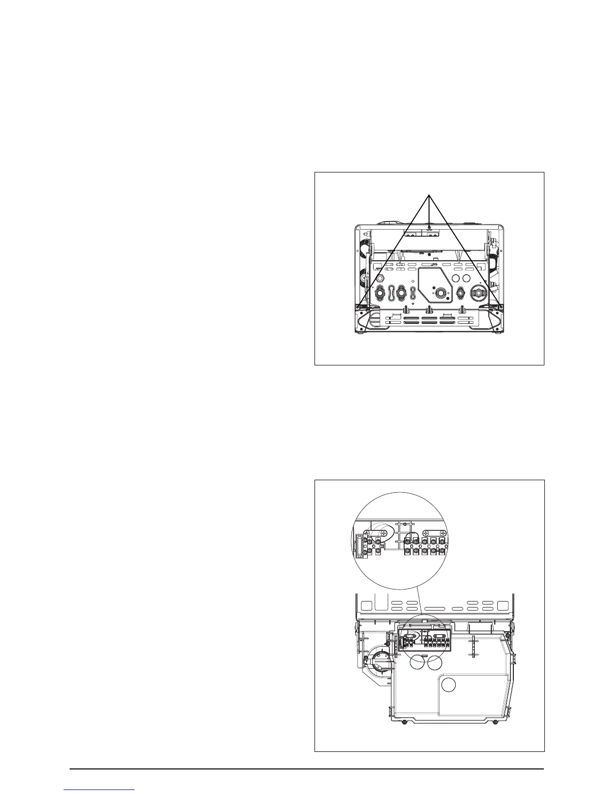
4.7.1 CASING REMOVAL
To gain access to the appliance electrical
connections you must first remove the casing,
proceed as follows:
● Locate and remove the 3 screws that secure
the outer casing to the appliance (fig 13).
● Gently pull one side of the casing then the other
to disengage it from the retaining clips.
● Lift the casing upward to disengage it from the
top locating hooks and then remove.
● Store the casing and screws safely until
required. Re-fit in the reverse order.
4.7.2 ELECTRICAL CONNECTION
The appliance terminal strip is located behind the
control fascia (fig. 14).
NOTE
If it is anticipated that external controls will be
required please refer to the wiring diagrams in
section 8 for more detailed information.
Control panel screws and casing screws
Fig. 13
Fig. 14