Do you have a question about the Volkswagen Marine TDI 100-5 and is the answer not in the manual?
| Engine Type | Diesel |
|---|---|
| Number of Cylinders | 5 |
| Displacement | 2.5 L |
| Power Output | 100 HP |
| Fuel System | Direct injection |
| Engine Configuration | Inline |
| Aspiration | Turbocharged |
| Cooling System | Water-cooled |
Describes key characteristics of the boat engines, including quiet operation, low weight, and advanced electronics.
Details the naturally aspirated diesel engines designed for displacement boats with direct injection.
Presents technical specifications and performance curves for the SDI engine models.
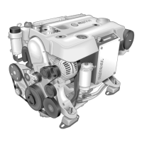
Explains the turbocharged direct injection engines designed for various boat types.
Provides technical specifications and performance curves for the TDI engine models.
Illustrates the system for circulating engine oil, including filter and extractor pump.
Describes the upright, easily serviceable cup-type oil filter and its function.
Explains the electric pump for environmentally friendly engine oil changes.
Details the specially designed oil pan with baffle plates for stability in rough seas.
Describes the system for cleaning crankcase air and preventing oil deposits.
Covers toothed belt drives for camshaft, coolant pump, and injection pump.
Details V-belt drives for alternator, power steering, and seawater pump.
Explains the function of the dual-mass flywheel in reducing torsional vibrations.
Describes the hydraulic tappets that reduce noise and simplify servicing.
Explains direct fuel injection into the combustion chamber and its advantages.
Details the intake port design that creates a swirling motion in the intake air.
Describes how the piston recess continues the swirling air motion for optimal combustion.
Covers the five-hole injection nozzle and its two-stage injection process.
Explains the two-spring nozzle holder for smooth, two-stage fuel injection.
Provides a general layout of the Marine Diesel Control (MDC) system components.
Shows how sensors supply information to the engine control unit for operating status.
Details the integrated glow plug control system functions: preheating, post-heating, standby.
Describes the sensor in the intake manifold measuring pressure and air temperature.
Explains the sender on the injection nozzle that signals the start of injection.
Covers the sender that signals the position of the metering adjuster in the injection pump.
Describes the sensor that detects engine speed using the induction principle.
Explains the NTC sensor that provides engine temperature data to the control unit.
Details the sender measuring fuel temperature to adapt injection volume.
Covers the sender that informs the control unit of the throttle lever position.
Describes the electromagnetic actuator controlling injection volume in the distributor injection pump.
Explains the valve controlling the start of fuel injection based on pulse duty factor.
Details the solenoid valve that interrupts fuel supply to shut down the engine.
Explains the self-diagnosis indicator lamp for malfunctions.
Describes how sensor signals determine injection volume and control the metering adjuster.
Explains how the control unit determines correct fuel delivery timing.
Details the mechanical device that adjusts injection timing based on fuel pressure.
Covers how the control unit maintains a constant idle speed by adjusting the metering adjuster.
Explains how injection volume per cylinder is controlled for uniform engine operation.
Describes how injection volume is reduced to protect the engine at maximum speed.
Details how starting injection volume is determined based on coolant temperature.
Explains the self-monitoring of sensors and actuators with visual/acoustic warnings.
Presents a schematic diagram illustrating electrical system connections and components.
Describes the system for supplying fuel from the tank to the injection pump.
Explains the filter for impurities and its water level warning system.
Details the filter that separates water and particles from the fuel.
Discusses the importance of low environmental pollution and engine design.
Identifies and describes common exhaust gases like CO, HC, soot, and NOx.
Explains measures taken to reduce exhaust gas constituents like soot and HC.
Explains how turbochargers increase engine torque and output by compressing intake air.
Details the turbocharger with variable guide vanes for optimal boost pressure.
Describes how the pressure cell controls guide vane positions based on intake manifold pressure.
Explains the mechanism for adjusting guide vanes via a control linkage.
Explains the dual-circuit cooling system used in boats to transfer heat to seawater.
Illustrates the cooling circuit design for SDI engines.
Describes the flow of seawater through the system for cooling the engine.
Details the primary coolant circuit used during engine warm-up.
Explains the primary coolant circuit used once the engine reaches operating temperature.
Illustrates the cooling circuit design for TDI engines, including the intercooler.
Shows the layout of the intercooler, main heat exchanger, and expansion tank.
Describes the intercooler that cools compressed charge air using seawater.
Explains how heat is transferred from coolant to seawater.
Details the exhaust header that is cooled by the coolant circuit.
Describes how seawater is fed to the exhaust manifold for cooling.
Explains the cooler that cools fuel, hydraulic oil, or gear oil.
Details the pump driven by a V-belt that circulates seawater.
Explains the anode in the heat exchanger that prevents corrosion.
Describes the unit housing the engine control unit, relays, and fuses.
Explains the relay that temporarily connects the engine to earth for starting.
Details the display showing operating hours, distance, fuel consumption, and speed.
Describes the automatic memory function of the multifunction display.
Covers information provided by the rev counter, voltmeter, and oil pressure gauge.
Explains the system diagnosis function for reading malfunctions from the fault code memory.
Describes how to check the control unit identification.
Details how to check and read stored fault codes from the memory.
Explains how to check the functionality of engine actuators.
Covers the initiation of basic settings for the injection pump.
Describes how to delete entries from the fault code memory.
Explains how to end communication with the engine control unit.
Details how to read engine operating data using the diagnosis system.
Illustrates common fault displays and their functional descriptions.
Explains how sensors are monitored for plausible signal voltages.
Lists available gearbox bell housings for different drive systems.
Provides a comprehensive list of abbreviations and their meanings used in the manual.
