MCC to engine extension cable, 8-pin
Feet Meter Part no.
9.8 3 874414
16.4 5 874119
22.9 7 874386
29.5 9 874387
36.1 11 874388
2-pin plug
H = 11 mm (0.43”)
W = 16 mm (0.63”)
D = 18 mm (0.71”)
W
H
D
Input Connection
Part no.
21350704
47705609 03-2014
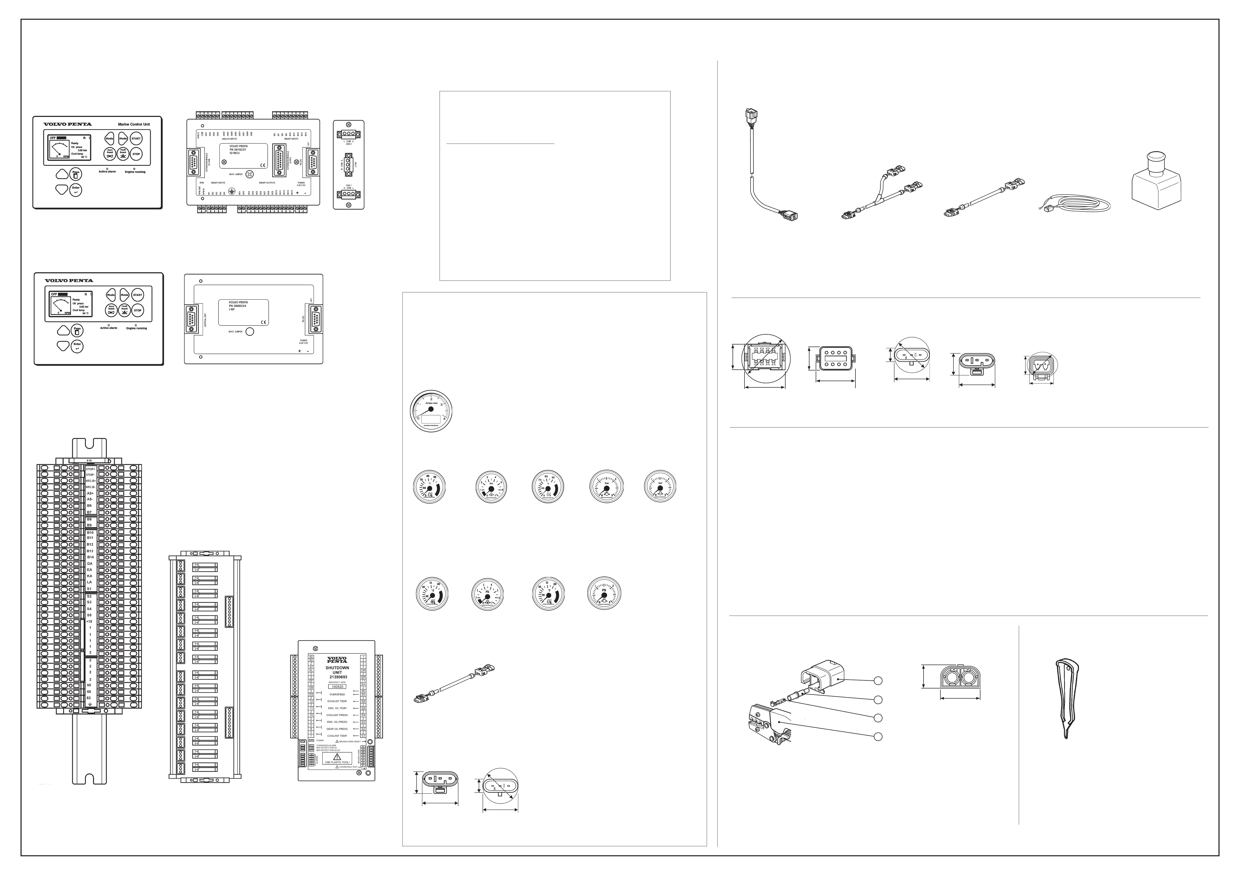
Components and Cables
Cables
External stop switch cable,
2-pin
Feet Meter Part no.
32.8 10 3840677
Water in fuel cable harness,
3-pin
Feet Meter Part no.
9.8 3 21415866
16.4 5 21415883
Water in fuel Y-Split cable harness, 3-pin
Part no. 21495971
Connector dimensions
Secondary Battery (backup) Connection (D9/D16) and
Primary battery Connection (D16 only)
Input Connection Tool
8-pin female
H = 20 mm (0.78”)
W = 37 mm (1.45”)
2-pin
H = 15 mm (0.59”)
W = 24 mm (0.94”)
8-pin male
H = 20 mm (0.78”)
W = 37 mm (1.45”)
D = 43 mm (1.69”)
Components
MCU Marine Control Unit
Part no.
3818237
Remote Panel
Part no.
3888244
SDU - Shutdown Unit
Part no.
21350693
Spare part no.
(includes reference to calibration document)
3819845
External Stop Switch
Part no.
3589458
NO/NC contacts
Cable not included. Use External
Stop Switch Cable Part no. 3840677
Relay Connection
Part no.
3818362
Remote Panel
Crimping parts
Part Part no.
1. Housing* 1307049
2. Isolator* 1608765
3. Pin* 969832 (2,5 mm
2
/13 AWG) Max. insulation diam. 3,1 mm (included in engine harness)
Pin 948291 (2,5 mm
2
/13 AWG) Max. insulation diam. 4,5 mm (not included)
4. Crimping tool 951 2653
* Included in engine delivery.
Remove the blind plugs before crimping.
Tool
Part
Tool Included in Steel box MCC
Front View
Front View
Rear View
Rear View
3
2
1
4
D
W
H
H
H
W
3-pin male
H = 18 mm (0.71”)
W = 26 mm (1.02”)
D = 26 mm (1.02”)
3-pin female
H = 20 mm (0.79”)
W = 25 mm (0.98”)
D
H
H
BL
BL
Optional Engine Instruments (Easy Link)
Box
W
W
W
EasyLink ,
3-pin
Feet Meter Part no.
3.3 1 874759
9.8 3 3807043
3-pin male
H = 18 mm (0.71”)
W = 26 mm (1.02”)
D = 26 mm (1.02”)
3-pin female
H = 20 mm (0.79”)
W = 25 mm (0.98”)
H
H
W
W
Instruments
Part Part no.
Tachometer 874903
Attachment ring 874449 Hole 85 mm (3.35”)
Front ring 874447
Instruments US setup
Oil temp (C°)
Color Part no.
Black 874905
White 874922
Oil pressure (Bar)
Color Part no.
Black 874908
White 874923
Coolant temp (C°)
Color Part no.
Black 874904
White 874921
Coolant pressure (Bar)
Color Part no.
Black 874911
Turbo pressure (Bar)
Color Part no.
Black 874910
White 874924
Oil temp (F°)
Color Part no.
Black 881857
White 881858
Oil pressure (psi)
Color Part no.
Black 874919
White 874932
Coolant temp (F°)
Color Part no.
Black 874918
White 874931
Turbo pressure (psi)
Color Part no.
Black 874920
White 874933
Tachometer (rpm, h)
Engine speed and hours
Part no. 3837995
H = 222 mm (8.74”)
W= 146 mm (5.78”)
D = 100 mm (3.93”)
Cables
Connector dimensions
D
Use with Attachment ring: Part no. 874450. Hole diam. 52 mm (2.04”)
Use with Attachment ring: Part no. 874450. Hole diam. 52 mm (2.04”)
For installation of tachometer and max. three other instruments, see below.
Terminal block / relay connections
CAN communication. Shielded, pairtwisted
Secondary Battery
Battery cables
RS232 / MODBUS. Shielded, pairtwisted
ID-COM
Part no.
3818364
Category A
Crosscut area minimum 1,5 mm
2
(16 AWG) type approved low voltage (30 V or more) ship cable, Max 50 meters (164 ft)
Category B
Crosscut area min. 0,25 mm
2
(23 AWG) 120 Ohm nominal impedance, Maximal attenuation (at 1 MHz) 2 dB / 100 m (328 ft), Max 900 meters (2953 ft) Nominal Velocity of Propagation min. 75% (max. 4,4 ns/m)
Category C
Crosscut area 2,5 mm
2
(13 AWG) type approved low voltage (30 V or more) ship cable, Max 30 meters (98 ft)
Category D
Refer to Installation manual D5-D16 Publ. no: 47704151 for dimensions.
Category E
RS232: Use signal cable with 2-3, 3-2, 5-5 cable (max. 10 meter / 32.8 ft). Note! MODBUS failures will occur if 9 to 9 pin cable is used.
RS485/422: Less than 40 meters (131 ft): Crosscut min. 0,75 mm
2
, (18 AWG) 120 Ohm impedance, Max. attenuation (at 1 MHz) 1,7 dB / 100 m (328 ft)
RS485/422: Longer than 40 meters (131 ft): Drain wired, crosscut min. 0,75 mm
2
(18 AWG) 120 Ohm impedance, Max. attenuation (at 1 MHz) 1,7 dB / 100 m (328 ft)
Note!
PRP
PRP
MCU / Remote Panel Engine Data
Engine Speed X
Load X
Fuel Rate X
Actual Torque X
Demand Torque X
Throttle pos X
Oil Press X
Oil Temp X
Coolant Press X
Coolant Temp X
SeaWaterPres* X
Exhaust Temp X
ChrgAirPress X
ChrgAirTemp X
Fuel Press X
CrankcasPres X
*Depends on cooling system.
Indicator Propulsion
 Loading...