Do you have a question about the Volvo B5244S4 and is the answer not in the manual?
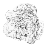
Introduces engine compactness, mounts, integrated components, drive belts, and management systems.
Details the B5244S4 engine, its basis, introduction, emissions, and transmission.
Details crankshaft stroke, weight, bearing journals, and bearing material.
Details connecting rod length, weight, and bearing material.
Describes graphite-coated pistons, their dimensions, weight, and coating.
Details cylinder head features, CVVT, and angle variation.
Mentions integrated sensors, CVVT solenoid location, and oil filler pipe.
Describes integrated oil filter/trap, its location, overflow valve, and oil separation.
Discusses spark plug features like Quick Heat, thread length, and electrodes.
Covers thermostat housing location and auxiliary equipment design changes.
Describes the Under Floor Catalyst (UFC) and its ceramic monoliths.
Mentions reduced wind resistance and pipe/tail pipe specifications.
Details intake manifold sections, volume, injector location, material, and crankcase gas ducts.
Discusses air cleaner design for pressure drop and compactness, and its housing.
Mentions cooling fan speeds and blades.
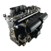
Details the B5254T3 engine, its basis, management system, emissions, and transmission.
Details crankshaft stroke, weight, bearing journals, and bearing material.
Details connecting rod material and bearing type.
Describes graphite-coated pistons, their dimensions, weight, and coating.
Details cylinder head features, CVVT, and angle variation.
Describes integrated oil filter/trap, its location, overflow valve, and oil separation.
Discusses spark plug features like Quick Heat, thread length, and electrodes.
Identifies timing belt pulley, lock pin, rotor, and rotor wings.
Describes how the CVVT unit adjusts camshaft position relative to the crankshaft.
Explains how the timing belt pulley and rotor are secured in the 0 position.
Explains that the ECM controls the valve using a PWM signal for oil flow.
Describes oil flow, lock pin engagement, and CVVT unit release.
Explains rotor rotation due to oil pressure and return oil flow.
Describes oil flow, clockwise rotor rotation, and lock pin engagement.
Mentions rapid process, ECM control for advancing/retarding, and high frequency.
Discusses ME 7.01 to ME 9.0 update and control module relocation to intake manifold.
Compares processor load, flash memory, and margin for ME 9.0 vs ME 7.01.
Highlights ME 9.0's higher temperature and vibration specifications.
States exhaust manifold integrated with turbine housing and MLS gasket.
Mentions maximum charge pressure and Turbo Control Valve (TCV) location.
Details turbocharger matching and design by Volvo and 3k-Warner.
Describes the Under Floor Catalyst (UFC) with double oval ceramic monoliths.
Covers intercooler location and charge air pipe mounting.
Describes intake manifold sections and ETB with shortened hose connector.
Covers auxiliary equipment design and thermostat housing location.
Details intake manifold sections, volume, injector location, material, and crankcase gas ducts.
Discusses air cleaner design, housing, and integration.
Details plastic fuel tank for U.S. (LEV II) and its volume.
Describes the EVAP system, recirculation pipe, and EVAP canister.
Explains PEM function and mounting location.
Details pump flow rates for NA and turbo engines at full load and idle.
States power consumption variation based on engine load.
Explains PVV operation and pressure limitation for NA and turbo engines.
States the PRV opens within a specific pressure range for B5244S4.
Explains FFV function for filling and tilt conditions.
Explains check valve function and ejector operation.
States fuel filter location within the reservoir.