The following signals are sent out on the network
from the Transmission Control Module (TCM) and
taken up by the Engine Control Module (ECM):
- Request for torque limiting step I and II
- Request to light Malfunction Indicator Lamp (MIL)
- Signal for constant idle speed compensation (P/N
position)
- Engaged gear.
Diagnostic Connector
The serial communication via the Diagnostic Con-
nector is used when reading off the Volvo onboard
diagnostic (OBD) system.
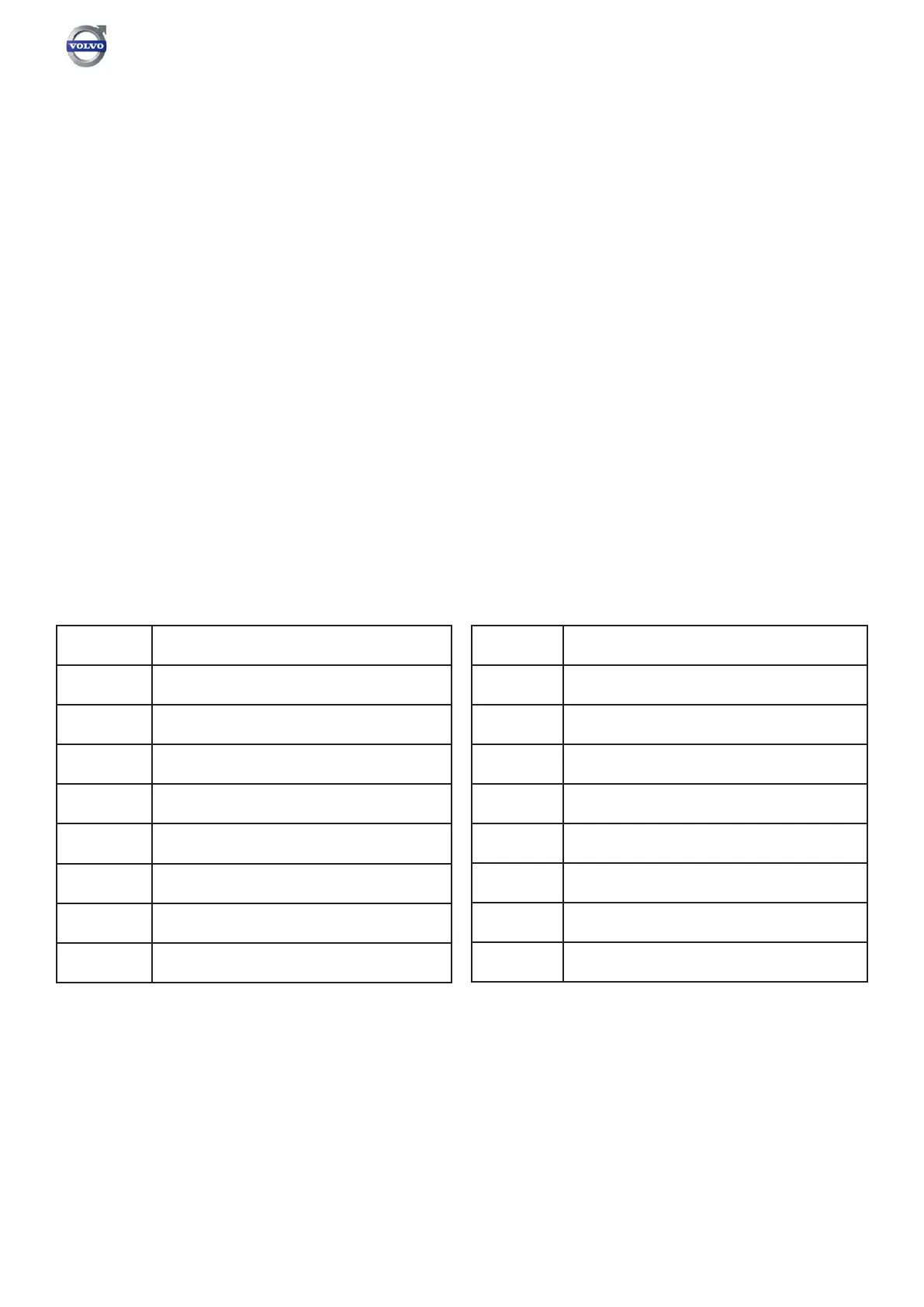
Contact General allocation
1 Discretionary
2
Not Connected
3 MS_CAN (Manufacturer spec)
4 Chassis ground
5 Signal ground
6
CAN_H line of ISO 15765-4
7 Not Connected
8 Discretionary
Contact General allocation
9 Discretionary
10
Not Connected
11 MS_CAN (Manufacturer spec)
12 Discretionary
13 Discretionary
14
CAN_L line of ISO 15765-4
15 Not Connected
16 Permanent positive voltage