Valve lash adjustment(2)
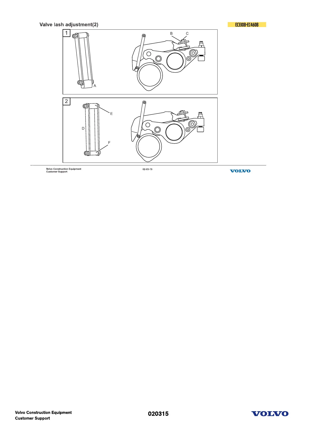
1. Adjustment
Insert a special adjustment gauge (A) tool (P/N: 88820003-1) between the follower arm contact surface
and the cam base circle.
Turn the hex key until the gauge is squeezed tight between the cam lobe and the follower arm contact
surface.
Tighten the nut (B), while piston (C) is kept in position.
Tighten the oil drain nipple.
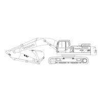
2. Inspection
Insert a special go/no go gauge tool (D) (P/N: 88820003-2) between the follower arm contact surface and
the cam base circle. The go gauge side (F) must pass through between the follower arm surface and the
cam base circle; if not the IEGR lift will be too big.
Insert the opposite, no-go, side (E) between the follower arm contact surface and the cam base circle. The
no-go gauge side must not pass through; if it does the IEGR lift will be too small.
If the IEGR valve lash does not pass the inspection, the lash has to be readjusted.
Picture text:
1. Nut (lock)
2. Piston