VECU input & output
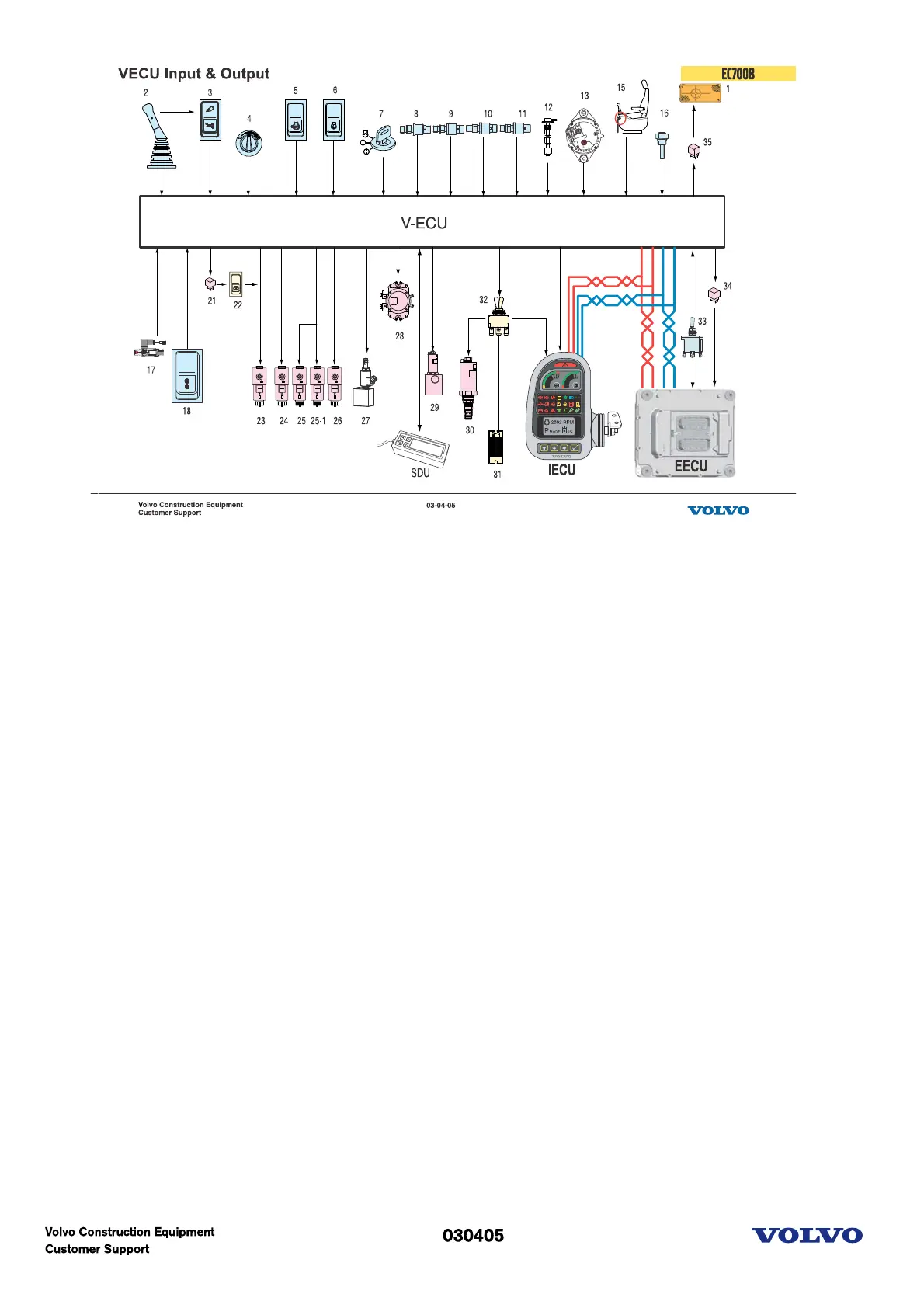
This diagram shows the primary input and outputs based on the connection found within the VCEU
circuitry. Input factors (communications) can be divided into two broad categories. One category relates to
selection switches which send a signal to the VECU initiated by the operator. The other, relates to
combined parts that are composed of hydraulic and electric components such as solenoid valves or
pressure limit switches.
The following are associated with the VECU:
1. Alarm(Travel or swing)
2. Boom float switch on the RH side of the RCV
3. Hammer and shear selection switch
4. Engine speed control switch
5. Power max selection switch
6. Auto idle selection switch
7. Start switch
8. Boom float position pressure switch
9. Travel pilot pressure switch
10. Attachment pilot pressure switch
11. Hammer pilot pressure switch
12. Fuel level sensor
13. Alternator 'L' signal (Lamp)
15. Safety lever
16. Hydraulic oil temperature sensor
17. Overload pressure switch
18. Overload switch
21. Travel speed relay
22. Travel speed selection switch
23. Travel speed solenoid
24. Boom floating solenoid
25. Boom/Arm conflux cut-off solenoid
26. Power boost solenoid
27. Hydraulic oil cooler fan control proportional relief valve


 To Next Page