L
LR
16
V1182188
5
3
4
1
6
7
8
10
15
2
17
13
14
9
11
12
e
f
t
n
t
r
l
e
v
i
g
t
n
t
r
l
e
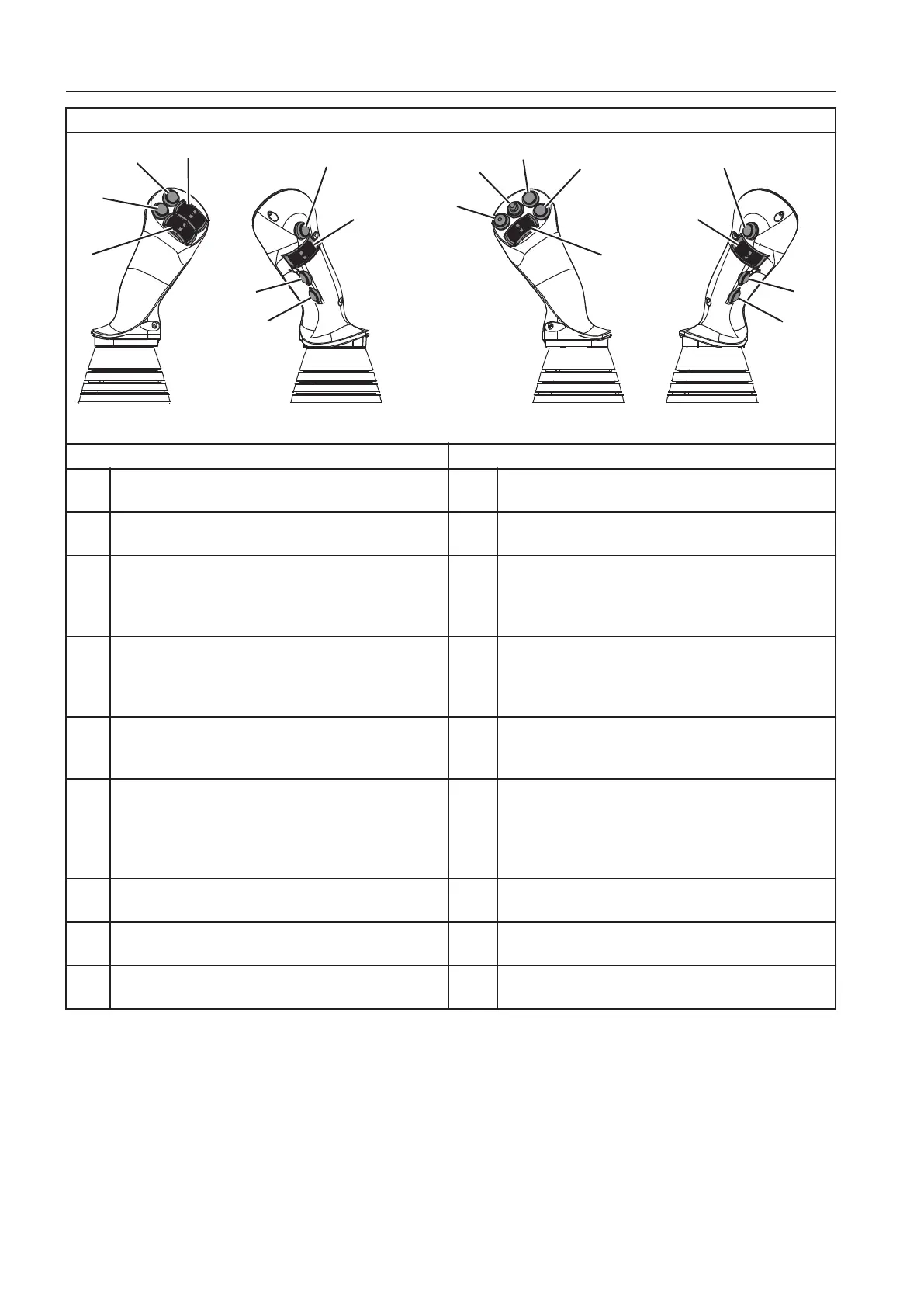
1. X
e
f
t
t
t
a
e
(see page
102
and
79
)
9. U
s
g
e
d
2. H
o
r
10. G
r
p
e
r
p
i
l
q
u
p
m
)
(see page
102
)
3. P
v
t
x
c
n
g
(see page
150
)
11. C
i
n
(see page
108
)
o
r
e
e
r
s
p
t
i
o
n
f
e
l
w
s
s
s
a
l
l
e
d
4. A
d
i
t
i
o
n
a
r
l
o
u
n
i
o
e
e
l
w
s
U
)
(see page
58
)
12. C
i
n
w
n
(see page
108
)
o
r
e
e
r
s
p
t
i
o
n
f
e
l
w
s
s
s
a
l
l
e
d
5. J
y
i
t
r
l
l
e
p
o
t
i
n
l
q
u
i
m
n
)
(see page
34
)
(not in combination with Two-Piece offset boom)
13. F
l
o
a
t
o
t
i
n
(see page
222
)
6. C
D
C
p
t
i
o
a
q
u
i
p
m
n
)
(see page
161
)
14. S
o
r
k
y
(see page
58
)
o
r
w
-
i
e
f
s
o
o
p
i
o
n
u
i
)
(see page
227
)
7. U
n
a
s
g
e
15. P
w
e
o
(see page
222
)
8. U
n
a
s
g
e
16. X
e
t
t
i
l
t
(see page
102
and
79
)
17. F
o
r
t
r
a
r
r
v
l
i
r
i
(see page
160
)
3
n
t
o
l
e
s
i
p
t
i
n
The X3 function is used to control attachment tools with a lower
limited oil flow.
The oil flow for the X3 function can be set in the IC (Instrument
Cluster), see page
58
.
The function is controlled by the left control lever.
There are three control types (push, toggle or proportional) which
can be selected in the IC (Instrument Cluster), see page
79
.
For the hydraulic pressure/flow specifications and for the
connection port specifications, see
350
9
8
t
h
e
r
n
t
r
o
l
s
o
n
t
r
o
l
s