Do you have a question about the Volvo TAD734GE and is the answer not in the manual?
General safety rules and precautions for working with the EMS 2 system.
Details about the manual's content, scope, and application to engine models.
Information on using Volvo Penta Original Spare Parts for system maintenance.
Requirements for servicing emission-certified engines and warranty implications.
Essential advice to prevent damage to engine control units and electronics.
Methods for checking connectors, terminals, and cables for faults.
Steps to check alternator belt tension, connections, and battery charging.
Procedure for measuring rail pressure using a multimeter and adapter cable.
Overview of the EMS 2 electronic system for diesel engine control.
How the EMS 2 electronically controls fuel injection amount and advance.
Purpose of the diagnostic function to identify and report system malfunctions.
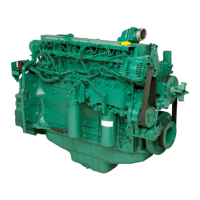
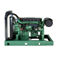
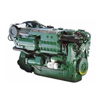
Diagram showing component locations on TAD 650, 660, 750, 760 VE engines.
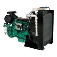
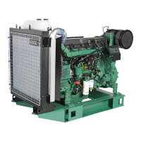
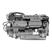
Diagram showing component locations on the TAD 734 GE engine.
Explanation of how injectors are controlled and their function in fuel delivery.
Details on the inductive crankshaft speed sensor and its signal.
Description of the combined sensor measuring boost pressure and temperature.
Description of the engine oil pressure sensor and its function.
Description of the sensor measuring fuel pressure in the common rail.
Details of the EMS 2 unit, its processor, and the information it receives.
Explanation of fault code components: MID, PID, PPID, SID, PSID, FMI, SPN.
Standard SAE Failure Mode Identifier (FMI) codes and their display/text explanations.
Description of CAN and J1587 communication buses used in the system.
Procedures for manually tracing faults in bus cables using a multimeter.
Troubleshooting for inlet air heater status faults including FMI codes.
Troubleshooting for fuel pressure issues, including FMI codes and fault tracing.
Troubleshooting for oil pressure faults, including FMI codes and possible reasons.
Troubleshooting for rail pressure faults, including FMI codes and symptoms.
Troubleshooting for crankshaft speed sensor faults, including FMI codes and circuit descriptions.
Troubleshooting for engine starter relay faults, including FMI codes and circuit descriptions.
Troubleshooting for J1939 communication faults between EMS2 and DCU/CIU.
Map detailing engine derating parameters based on temperature and pressure.
Wiring diagram for the EMS2 vehicle harness on TAD650-760VE models.
Wiring diagram for the EMS2 engine harness on TAD734 GE models.
Wiring diagram for the Display Control Unit (DCU).
Wiring diagram for the Control Interface Unit (CIU).
Technical specifications for the fuel pressure sensor.
Technical specifications for camshaft and crankshaft speed sensors.
Technical specifications for the engine oil pressure sensor.
Technical specifications for the rail pressure sensor.
Technical specifications for the alternator, including voltage and capacity.
Technical specifications for the starter motor, including voltage and capacity.
| Engine Model | TAD734GE |
|---|---|
| Cooling System | Liquid-cooled |
| Displacement | 7.15 liters |
| Bore x Stroke | 108 x 130 mm |
| Aspiration | Turbocharged |
| Fuel System | Electronic Unit Injectors (EUI) |
| Engine Speed | 1500 rpm |
| Emission Level | EU Stage II |
| Engine Type | 4-stroke, 6-cylinder in-line diesel engine |