Do you have a question about the Volvo TAD1344GE and is the answer not in the manual?
General information about the service manual's content, purpose, and target audience.
Specific requirements and demands for service and repair on emission-certified engines.
General guidance on working methods, safety warnings, and handling of chemicals.
Emphasizes adherence to technical specifications, use of genuine parts, and maintenance intervals.
Guidelines for torque/angle tightening, reuse of lock nuts, and strength classes of fasteners.
Information on RTV preparations and anaerobic agents used for sealing and locking.
Safety precautions when handling fluorocarbon rubber seals due to potential hazards from decomposition.
Important handling instructions for the engine's viscous fan to prevent seizure.
Standard torque values for various bolt sizes (M6 to M16) with strength class 8.8.
Re-installation guidelines for angle-tightened bolts based on strength class (8.8, 10.9, 12.9).
Detailed torque specifications for engine component assemblies like mountings and bearing caps.
Step-by-step torque and angle tightening procedures for main bearing caps and engine mountings.
Tightening sequence and torque specifications for frame reinforcement and timing gear plate bolts.
Torque specifications for various timing gear components including crankshaft, idler, and camshaft gears.
Torque specifications for flywheel housing bolts and timing gear cover bolts.
Two-stage installation procedure and torque specification for the upper timing gear cover.
Tightening and angle procedures for flywheel bolts and crankshaft seal cover.
Torque specifications for crankshaft vibration damper and cylinder head bolts.
Multi-stage tightening and angle procedures for camshaft and rocker arm shaft bearing caps.
Torque and angle specifications for valves, EGR rocker arms, and spring plates.
Torque specification for tightening the valve cover bolts.
Procedures and torque values for installing the oil sump and its drain plug.
Torque specifications for oil cooler attachment bolts and cover bolts.
Torque specifications for thermostat valve, safety valve, and overflow valve.
Torque and angle tightening procedures for unit injector yoke and adjuster screw locknut.
Torque specification for bolts attaching the fuel pump adapter and the fuel pump.
Tightening torques for various fuel line brackets (A through F).
Torque specifications for inlet manifold bolts and exhaust manifold bolts.
Identification and torque specifications for various engine sensors.
Reference to general tightening torques for cooling system components.
General specifications and dimensions for the engine, including cylinder details and weights.
Technical data for engine body, cylinder head, block, liner, and piston dimensions.
Specifications for compression and oil scraper rings, including quantity, clearance, and gap.
Dimensions and wear values for valve heads, stems, seats, and cylinder head sealing surfaces.
Specified valve clearances and EGR rocker arm adjustment procedures.
Check value for EGR rocker arm play and dimensions for valve seats.
Dimensions for valve seat diameter, depth, and radius; valve guide length, diameter, and wear values.
Wear values for rocker arm play and uncompressed lengths for valve springs.
Details of timing gear components and specifications for gear lash and clearance.
Specifications for camshaft drive, bearing journals, wear, and camshaft bearing thickness.
Wear values and machining specifications for the crankshaft, including journals and runout.
Diameter, surface fineness, width, and fillet radius specifications for main bearing journals.
Standard and oversize dimensions for thrust washer width and main bearing cup thickness.
Specifications for big-end journals and connecting rod dimensions.
Standard and oversize dimensions for connecting rod bearing cup thickness.
Connecting rod marking, wear values, and flywheel runout specifications.
Technical data for engine oil capacity, pressure, and temperature.
Identification of oil filters and opening temperature for the thermostat oil valve.
Technical data for fuel feed pump and bypass valve pressures.
Technical data for the pressure drop indicator's operating voltage.
Technical data for pressure cap, thermostat opening temperature, and coolant quantity.
Impedance values for the engine oil temperature sensor at various temperatures.
Impedance values for coolant and charge air temperature sensors across temperature ranges.
Specifications for pressure drop indicator, camshaft sensor, and crankcase sensor.
General safety information and explanation of warning symbols used in the manual.
Safety warnings regarding engine operation, hot surfaces, air filters, ventilation, and chemicals.
Safety warnings for eye protection, battery handling, flammable materials, and lifting heavy components.
Safety warnings for electrical/fuel systems, leak detection, high-pressure washers, and fuel pipes.
List of specialized tools for engine repair, with part numbers for ordering.
Further listing of specialized tools for tasks like draining, compression testing, and seal replacement.
List of miscellaneous equipment such as torque wrenches, magnetic stands, and dial indicators.
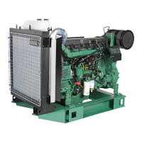
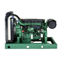
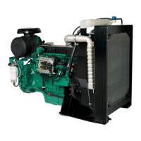
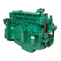
Overview of engine design and explanation of identification numbers (chassis, serial).
General description of the inline six-cylinder turbocharged diesel engine with EGR system.
Description of cylinder head construction, coolant thermostat housing, and porting.
Details on guide pins for correct valve cover fitting on the cylinder head.
Information on injector placement, coolant chambers, valve mechanisms, and valve guides.
Details on copper sleeves, O-rings, and steel gaskets for unit injectors.
Description of the cylinder block, including lubrication and cooling ducts.
Information on block side shape for stiffness and main bearing cap positioning.
Description of the engine stiffening frame and the composite oil sump.
Details on sealing mechanisms for wet cylinder liners, O-rings, and the cylinder head gasket.
Explanation of guide washers and timing plate for precise cylinder head installation.
Description of pistons, cylinder liners, connecting rods, and their markings.
Details on camshaft, valve train, rocker arms, and camshaft timing markings.
Description of the internal EGR system components and their operational principles.
Explanation of normal engine operation and the sequence of EGR activation.
Detailed steps 3 and 4 of the EGR activation and deactivation process.
Step 5 of the EGR deactivation process, involving pump piston return.
Description of crankshaft construction, bearings, seals, and gearwheel fastening.
Explanation of crankshaft lubrication, vibration damper function, and flywheel attachment.
Overview of engine timing gears, plates, and dampers.
Details on intermediate gears, their support, and adjustment procedures.
Description of engine timing gear covers, seals, and flywheel housing openings.
Overview of the engine's pressure lubrication system.
Details on oil flow control valves in the cylinder block, pump, and filter housing.
Diagram and explanation of lubrication system oil flow and valve functions.
Description of the lubrication oil pump and its pressure reduction valve.
Details on the suction system, connection pipes, and oil cooler mounting.
Illustration and explanation of piston cooling oil flow and nozzle aiming.
Description of the control valve's role in regulating oil pressure to the rocker arm mechanism.
Explanation of the control valve's neutral and normal operation positions.
Explanation of the control valve's role in EGR activation and deactivation.
Overview of the electronically controlled fuel injection system (EMS) and its components.
Diagram and explanation of the fuel feed system, including pumps, filters, and valves.
Details on filter operation, fuel pressure sensors, water separators, and hand pumps.
Explanation of unit injector operation phases: filling, spill, and pressure building.
Details on injection timing, ECU control, and injector trim code programming.
Description of fuel flow through the system, including check valves and venting.
Details on filter valve operation, fuel pressure sensors, and hand pump usage.
Detailed breakdown of unit injector parts and their operational phases.
Information on injector electrical connection markings and ECU programming requirements.
Illustration of exhaust manifold and turbocharger components.
Description of exhaust manifold construction and turbocharger by-pass valve operation.
Overview of the electronically controlled engine fuel system (EMS) and its sensors.
Explanation of the necessity for crankcase ventilation and its types (open/closed).
Description of open and closed crankcase ventilation systems and their components.
Table listing common engine symptoms, possible causes, and corresponding reason codes.
Common causes of cooling system interference and recommended actions for checks.
Tools and steps for removing unit injectors, adapters, and rocker bridge for compression testing.
Steps for connecting test equipment and performing the compression test on engine cylinders.
Steps for installing unit injectors, rocker bridge, and adjusting valves.
Procedures for checking fuel feed pressure and performing cooling system pressure tests.
Alternative methods for pressure testing the cooling system to detect leaks.
Procedures for checking charge air pressure and inspecting the exhaust system.
Checks for damage, clogging, and leaks in charge air coolers, pipes, and inlet manifolds.
Inspection of the turbocharger for correct part number, housing, and component integrity.
Steps for removing the turbocharger, including heat shield, pipes, and oil supply lines.
Steps for installing the turbocharger, spacer sleeves, nuts, and hoses, and checking for leaks.
Warning and important notes on draining the cooling system, followed by filler cap removal.
Safety warnings and procedures for flushing the cooling system with water and coolant.
Procedure for checking and topping up coolant levels in the expansion tank.
Alternative methods for pressure testing the cooling system to detect leaks.
Steps for draining coolant, removing belt guard, winding belt, and removing belt tensioner.
Steps for removing the coolant pump and installing a new one with gasket and pulley.
Steps for checking belt tensioner pulleys and winding on the belt.
Steps for removing and installing the belt tensioner.
Procedure for checking thermostat function by heating in water.
Steps for removing and installing the coolant filter.
Installation steps for the coolant filter, including lubricating the gasket and opening the tap.
Steps for removing and installing the right belt guard.
Removal and installation procedures for the left and upper belt guards.
Steps for removing and installing alternator belts by depressing the lever.
Steps for removing and installing the belt tensioner and alternator belt.
| Engine Model | TAD1344GE |
|---|---|
| Number of Cylinders | 6 |
| Displacement | 12.8 L |
| Fuel System | Common Rail |
| Cooling System | Water-cooled |
| Aspiration | Turbocharged |
| Emission Standards | EU Stage V |
| Engine Type | Diesel |
| Engine Speed | 1800 rpm |
| Bore | 131 mm (5.16 in) |
| Stroke | 158 mm |