Do you have a question about the Volvo XC90 PREMIER and is the answer not in the manual?
Extra caution must be exercised when working on vehicles equipped with SRS/SIPS bag/IC systems to avoid injury or damage.
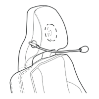
Guidance on how to recognize vehicles equipped with SRS, SIPS bags, and IC systems based on markings and features.
Precautions and best practices for working on or around SRS, SIPS, and IC components.
Defines abbreviations for groups, ignition switch symbols, countries/markets, and color codes.
Explains the meaning of symbols used for ignition switch positions.
Explains how components are identified by type and serial numbers.
Provides a list mapping component type numbers to their descriptions.
Describes how junction points are numbered and located in diagrams.
Explains how connectors are represented and described in the manual.
Explains CAN & MOST networks and data communication.
Explains various symbols used in wiring diagrams, including connections and communication types.
Presents a detailed overview of the electrical distribution system.
Details fuses located in the cargo compartment, specifically 11E and 11F.
Lists and describes fuses found by the vehicle's battery.
Lists and describes fuses located in the cargo compartment auxiliary fuse box.
Lists ground connection points and their associated components.
Details ground connections located at the A-post on the right-hand side.
Details ground connection points located between the front seats below the armrest.
Part 1 of the wiring diagram for the Rear Seat Entertainment system.
Part 2 of the wiring diagram for the Rear Seat Entertainment system.
Provides the wiring diagram for the Cooler system.
Details connector pin assignments for connectors 54/33 to 54/303.
Details the pin assignments for the 3-pin gray connector 54/33.
Details connector pin assignments for connectors 54/274 and 54/275.
Details connector pin assignments for connectors 54/276 and 54/277.
Provides wiring diagrams for junction points 53/403 to 53/521.
Provides wiring diagrams for junction points 53/522 to 53/731.
Illustrates the routing of the rear, RSE, and TV display harnesses within the vehicle.
Illustrations of the vehicle battery, various relays, and the ignition switch.
Illustrations of SRS control module, CEM, REM, starter motor, alternator, and sockets.
Illustrations of fuses, various speakers, microphone, TV displays, and DVD player.
Illustrations of Audio Module, RAS, AUX socket, RSE, IR transmitter, and ground connections.
Illustrations of connectors 54/274, 54/275, and 54/303.
| Brand | Volvo |
|---|---|
| Model | XC90 PREMIER |
| Category | Automobile |
| Language | English |