EasyManua.ls Logo

Von Duprin PS914 User Manual

Von Duprin PS914
20 pages
To Next Page IconTo Next Page
Page #1 background imageLoading...
Page #1 background image
1 of 4
These instructions cover the following parts:
Installation
Instructions
PS914 Power Supply
© 2010 Ingersoll-Rand Company
1-877-671-7011
44487056 Rev. 10/10_a
44487056
To avoid risk of electric shock, turn off AC power
before installing or servicing PS914 power supply.
DANGER:
!
PS914 Power Supply Specifi cations:
Input 120/240 VAC, 1.4 A, 50/60Hz, High Voltage Class 1 Wiring Required
Output 4 Amp DC @ 12/24 VDC
May be used to power Von Duprin & Falcon EL device at 24VDC, 16A, 300ms
Enclosure 14” H x 12” W x 4” D (8 knockouts, 1/2” or 3/4” )
Temperature Range 32°-120° F (0°- 49° C)
Fuse F1, T6.3A
250 VAC
Compliance UL 294, ULC-S318, RoHS, & FCC Part 15, Class 2 Output
Compatible Boards
(Optional, 2 boards maximum)
900-2RS
900-2Q
900-4R
900-4RL
900-8F
900-8P
Fire Alarm Input Board (Optional) 900-FA (Requires one option board above)
Battery Backup Board (Optional) 900-BB
AC Monitor Output Form C Contacts, 30 VDC, 1 Amp, Resistive Load
For protection against risk of fi re, replace fuse with same type and rating
CAUTION:
!
INST. INSTRUCTIONS - 44487056
INST. INSTRUCTIONS - 44487098
INST. INSTRUCTIONS - 44487106
INST. INSTRUCTIONS - 44487080
INST. INSTRUCTIONS - 44487106
INST. INSTRUCTIONS - 44487072
INST. INSTRUCTIONS - 44487064
Inputs I1,I2 Dry contacts required (Closed = Active)
Connect control contacts between SC (Signal Common) and any input
Outputs O1,O2 • 12/24VDC, 3A (wet) when AC powered • 9.6-13.2VDC or 19.2-26.4VDC when battery powered
• May be used with PS914 to power EL device at 24VDC, 16A, 300ms
• Maximum load cannot exceed power supply ratings or 3A for outputs combined
Board Input Power Board requires 0.1A max. of power supply output current to operate
Temperature Range 32°-120° F (0°- 49° C)
Compliance UL 294, ULC-S318, RoHS, & FCC Part 15
Fire Alarm Input Accepts 900-FA Fire Alarm Board (Optional)
900-2RS Specifi cations:
900-BB Battery Backup
(optional)
Page 3
900-2RS (optional) - Page 4
(2 Zone EL Control -
Individual/Sequential)
900-KL Keylock
(optional)
Page 2
PS914 Power Supply
Pages 1-3
F
1
DA
NGER
!
!
DAN
GER:
!
WA
RNING:
!
WARNING:
Question and Answer IconNeed help?

Do you have a question about the Von Duprin PS914 and is the answer not in the manual?

Von Duprin PS914 Specifications

General IconGeneral
BrandVon Duprin
ModelPS914
CategoryPower Supply
LanguageEnglish

Summary

PS914 Power Supply Specifications

PS914 General Specifications

Covers input/output voltage, enclosure, operating temp, and compliance.

Compatible Option Boards

Lists optional boards compatible with the PS914 power supply.

900-2RS Option Board Specifications

Details input/output, power, temp, and compliance for the 900-2RS board.

PS914 Installation and Setup

PS914 Mounting and Enclosure Security

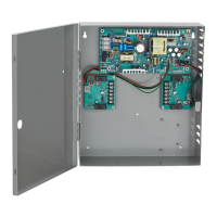
Outlines installation requirements and securing the power supply enclosure.

PS914 Setup, Testing, and AC Wiring

Guides on connecting AC power, selecting DC output, and verifying operation.

900-BB Battery Backup Installation

Installing the 900-BB Battery Backup Module

Instructions for installing the 900-BB board into the PS914.

900-2RS Option Board Installation and Wiring

Installing the 900-2RS Option Board

Steps for physically installing the 900-2RS board into the power supply.

Wiring Configurations for 900-2RS

Explains wiring for Individual and Sequential modes, including wire gauge tables.

900-4RL Option Board Overview

900-4RL Specifications

Details input/output, power, temperature, and compliance for the 900-4RL board.

Installing the 900-4RL Board

Instructions for mounting and connecting the 900-4RL board to compatible power supplies.

900-4RL Function Configuration

Selecting 900-4RL Board Functionality

Configuring the board's operation mode (4TD, AO, SI) using DIP switches.

Optional Dry Contact Configuration

How to configure outputs for dry contact operation instead of powered outputs.

900-4RL 4TD Function Details

Setting Time Delays for 4TD Function

Using SW1 DIP switches to set time delays for locking devices in 4TD mode.

4TD Input/Output Terminal Definitions

Explains the purpose of each input and output terminal for the 4TD function.

900-4RL 4TD Wiring Examples

4TD Fail Secure Wiring Example

Illustrates wiring for fail-secure locking devices with the 4TD function.

4TD Fail Safe Wiring Example

Illustrates wiring for fail-safe locking devices with the 4TD function.

900-4RL AO Function Configuration

Setting Auto Operator Signaling Options

Configuring auto operator signaling timing and modes using DIP switches.

AO Input/Output Terminal Definitions

Defines terminals for access control and auto operator signals.

900-4RL AO Wiring Examples

AO Wiring for Two Single Doors

Wiring diagram for AO function controlling two separate doors.

AO Wiring for Double Doors

Wiring diagram for AO function controlling two doors simultaneously.

900-4RL SI Function Configuration

Configuring SI DIP Switches and Interlocks

Setting up Security Interlock (SI) modes and global interlocks.

SI Input/Output Terminal Definitions

Defines terminals for access control, lock monitors, and outputs for SI function.

900-4RL SI Wiring and Troubleshooting

SI Wiring for Multi-Door Interlocks

Shows wiring for 2 to 6 door interlocks using the SI function.

Basic Troubleshooting for 900-4RL Functions

Provides guidance for common issues with the 900-4RL board's LED, inputs, and outputs.

900-FA Fire Alarm Input Board

900-FA Specifications

Details input/output, power, temperature, and compliance for the 900-FA board.

Installing the 900-FA Board

Instructions for mounting the 900-FA board onto compatible power supply or option boards.

900-FA Fire Alarm Input Wiring

900-FA Terminal Definitions and Wiring Examples

Explains terminal functions and provides wiring diagrams for various reset modes.

900-BB Battery Backup Specifications

900-BB Battery Specifications

Details battery life, type, and replacement part number for the 900-BB.

Installing the 900-BB Onto Main Circuit Board

Steps for physically mounting the 900-BB board onto the PS914 main board.

900-BB Battery Connection and Testing

Connecting Batteries to the 900-BB

Instructions for attaching battery wires and placing batteries in the enclosure.

Verifying Battery Backup LED Status

Guidance on checking the BB LED to confirm proper battery connection and charging.

Related product manuals