NS d
1
Tube d
3
d
4
a (mm)
(mm) O.D. x wall thickness (mm) (mm)
(brass/nylon)
NS 8 9.7 6 x 1 4.6 4.0 16
8 x 1/9 x 1.5 6.9 6.0 16
10 x 1.25 8.1 7.5 22
10 x 1/11 x 1.5 9.0 8.0 22
12 x 1.5 10.3 9.0 22
NS 12 15.2 6 x 1 4.6 4.0 16
8 x 1/9 x 1.5 6.9 6.0 16
10 x 1.25 8.1 7.5 22
10 x 1/11 x 1.5 9.0 8.0 22
12 x 1.5/14 x 2.5 10.3 9.0 22/26
12,5 x 1.25/14 x 2 11.2 10.0 22
16 x 2 13.6 12.0 25
Manual assembly tool
4.2.3 Protective cap
All plugs are supplied with a
protective cap to protect the
neck of the plug and the o-
rings from damage and dirt.
This protective cap should not
be removed until immediately
before final assembly.
6
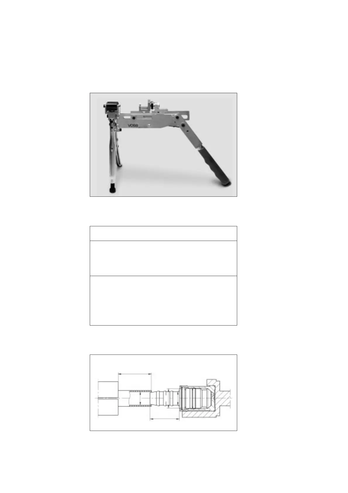
4.2.2 Insertion of the
fir-tree with manual
assembly tool
The tube clamping jaws
should be turned in the cor-
rect position until they match
the outer diameter of the tube
to be mounted. A tool insert
corresponding to the plug to
be fitted (NS 8 or NS 12,
straight or shaped plug)
should then be placed into
the fixture.
The diameter d3 of the fir-tree
should match the internal
diameter of the nylon tube
(see table). This ensures that
the required pretension pres-
sure of tube onto the fir-tree
is reached.
Next place the nylon tube in
the jaws, allowing it to pro-
trude by the length L (see
fig.), and firmly secure the
nylon tube by tightening the
vicegrip. The clamping force
exerted may be varied by
means of the adjusting screw.
The plug to be fitted should
then be placed in the tool
insert with a protective cap
and the transport bar pressed
manually towards the nylon
tubing until the fir-tree is pre-
centred in the tube end.
Now the nylon tube can be
pressed onto the plug as far
as the end of the fir-tree by
using the insert lever.
Outline of tube and plug dimensions
Possible combinations
of tube dimensions and fir-tree dimensions
L ≥ a+2 mm
d4
a
d1
d3
 Loading...