tection and pretension o-ring
while being pressed into the
coupling element, until both
clips snap into place in the
groove of the plug.
The first clip snaps into place
when only very little force is
applied. In this initial retention
position, the connection is
already secured against unin-
tentional loosening, but it is
not yet leak-tight. The con-
nection ist not fully sealed until
the second clip snaps into
Thread sizes Nominal size Across flats Tightening
torque
NS Nm
M 16 x 1.5 8 19 10 - 17
M 22 x 1.5 12 24 10 - 17
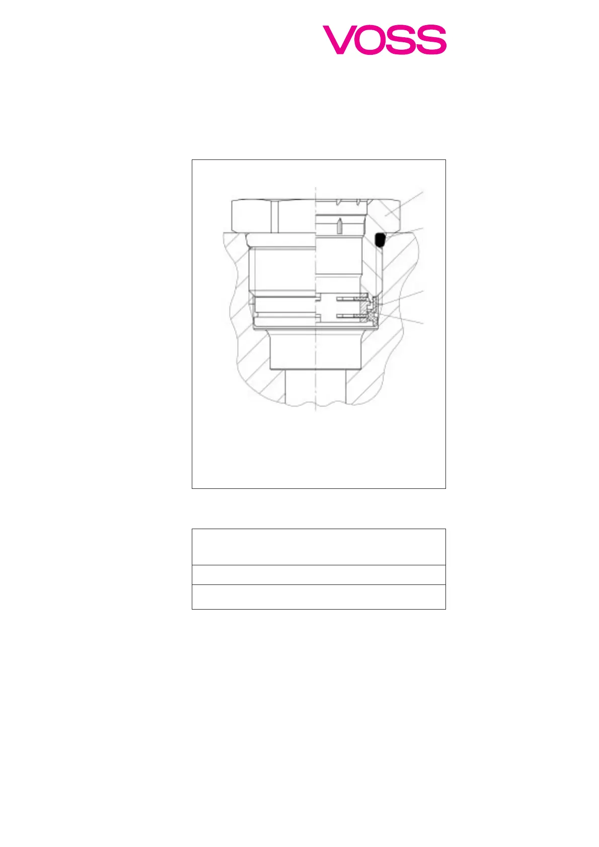
Coupling element:
1 Male nut Brass
2 Thread-sealing o-ring NBR 70
3 Fixing ring POM
4 Retaining element Spring steel/POM
4.3 Assembly of the
coupling element
In order to achieve safe func-
tioning, the connecting port
should be cleaned before fit-
ting the coupling element.
In particular, any residue of
paint still attached to the
region of the sealing lip should
be removed. Care is also be
taken to ensure that the
thread of the component is at
right angles to the contact
surface of the coupling ele-
ment.
The coupling element consists
of a male nut (1) with greased
thread-sealing o-ring (2) and
retaining element (4) clipped
into place with a fixing ring (3).
It is available from the factory
with or without paint protec-
tion stickers. If there is a paint
protection sticker on the front
of the coupling unit, it should
not be removed. The coupling
unit is screwed hand-tight
into the connecting port.
When the coupling element is
inserted into the thread, the
fixing ring acts to pre-align
the coupling element, thus
facilitating the assembly.
Now the coupling element
should be tightened with a
torque wrench. For this pur-
pose, the flap of the paint
protection sticker should be
folded upward. The recom-
mended tightening torques
are listed in table on the right.
The values quoted are valid
both for metal (die-cast alumi-
nium, die-cast zinc) and for
nylon casings (PA-GF30) with
VOSS V-thread.
Automatic VOSS assembly
tools are available on request
for high volume assembly.
7
4.4 Connecting line to
component
Now the protective cap can
be removed from the plug
(see section 4.2.3) and the
paint protection sticker can be
removed from the coupling
element (see section 4.3).
Slide plug with nylon tube fit-
ted to fir-tree into the port of
the coupling element. The
plug must overcome the axial
force exerted by the dirt-pro-
place. To conclude the inser-
for insertion. Always ensure
sit at a false angle in the port.
correctly fitted.
ring is not visible.
Incorrect connections, i.e.
bar). This will not result in
damage. Whether
installation location.
 Loading...