- 3 -
Connection
Plan:
Note:
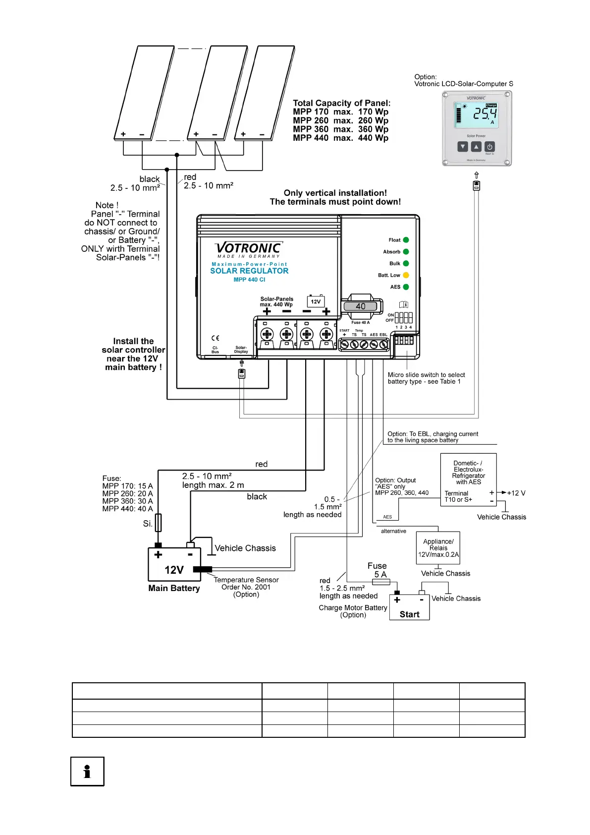
The connection plan shows the maximum terminal assignment for operation of all existing functions of the solar
controller. The minimum terminal assignment consists of the solar panel inputs ("+" and "-") and the connections to
the main battery.
Always connect the fuses as close as possible to the batteries (cable protection!).
Cut-off Relay:
The cut-off relay, which exists in most of the vehicles, can, of course, still be used. (For charging by the
dynamo, the cut-off relay connects the board battery to the starter battery during running motor of the
vehicle. The cut-off relay is not included in the connection plan).
Required Cable Cross-Sections, Notes MPP 170 CI MPP 260 CI MPP 360 CI MPP 440 CI
+/- Panel cables, length as required:
+/- Battery cables, length max. 2 m:
Fuse close to main battery:
 Loading...