ICON USER’S MANUAL: SECTION 7 VIRGINIA PANEL CORPORATION
7-3 For the most current information available, visit www.vpc.com.
6/7/18
CENTER BOSS
ICON ITA PROTECTIVE COVER ASSEMBLY AND INSTALLATION
PART # 410 112 750
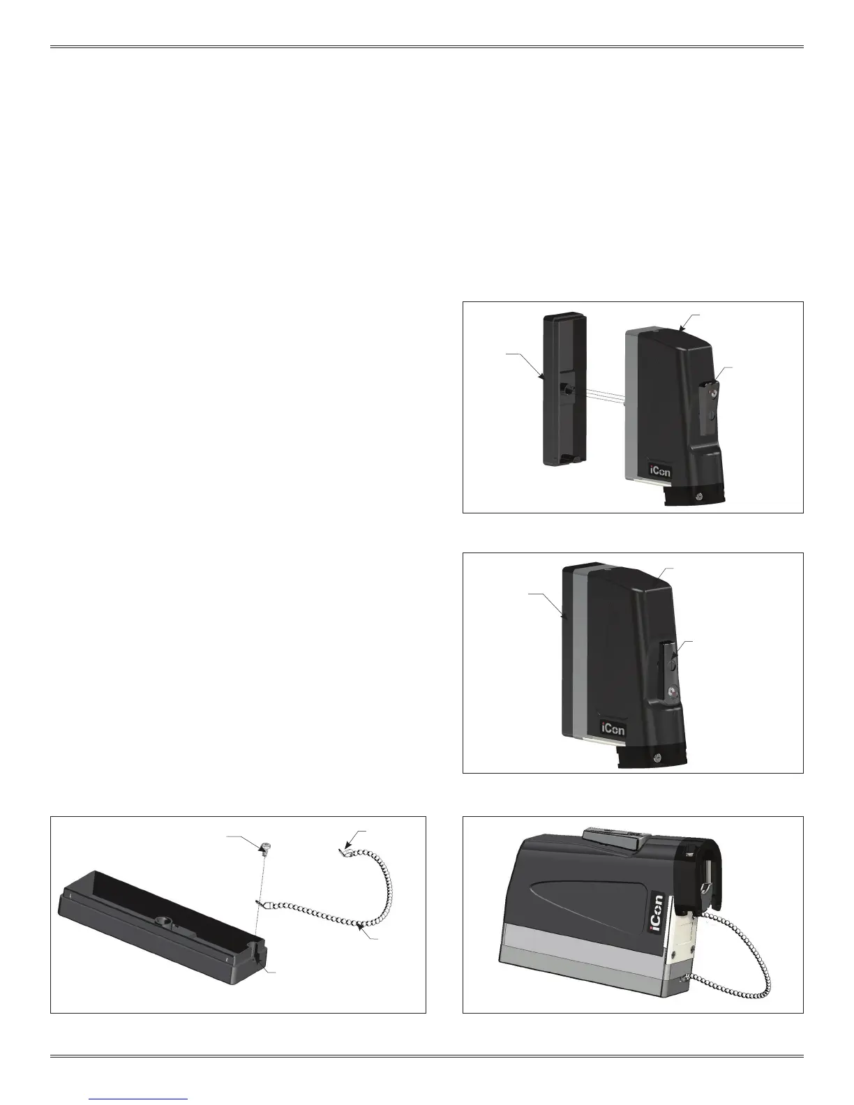
Figure A. When the engagement handle is open, the raised
circles will align and reveal the word “OPEN.”
ASSEMBLY INSTRUCTIONS
1. Move the iCon engagement handle to the open position.
2. Place the protective cover on the engagement mechanism
as shown in Figure A.
3. Turn the engagement handle to the closed position to fully
mate the iCon ITA and protective cover (Figure B).
INSTALLATION OF THE ITA PROTECTIVE COVER CHAIN
1. Attach one end of the chain to one of the supplied eyelets.
2. Attach the eyelet to the mounting hole in the protective
cover (Figure C).
3. Thread the chain through the mounting hole on the ITA base
(Figure D).
4. Attach the end of the chain to the end of the eyelet.
NOTE: A chain lanyard, protective cover, and hardware are
included with iCon ITA, part # 410 123 101.
Figure B. The triangles on the removable cover and
engagement handle align to indicate the closed position.
The ITA protective cover can be mounted to
a cabinet or enclosure if a permanent storage
location for the ITA is desired.
Figure C. The provided 4-40 screw has sharp angled threads to
easily secure the lanyard to the protective cover.
Figure D. This end of the eyelet can be attached using the
mounting hole on the ITA.
PROTECTIVE
COVER
PROTECTIVE
COVER
SUPPLIED
4-40 SCREW
ENGAGEMENT
HANDLE
IN OPEN
POSITION
ENGAGEMENT
HANDLE IN
CLOSED POSITION
SUPPLIED
CHAIN
CHAIN
MOUNTING
HOLE
ICON ITA
ICON ITA
SUPPLIED
EYELET
 Loading...